Simulation of SAW & BAW Resonators for RF Filters
Simulation of SAW & BAW Resonators for RF Filters

In this blog post, we’ll have a look at some of the basics of electronic resonators such as: what is a resonator, the types of resonators that are most used on the market, the basic physical principles, the most important characteristics, and how to get all of that with simulation using OnScale.
What is a resonator?
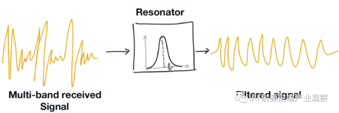
A resonator is an electronic device which vibrates at a very specific frequency. Resonators form an integral part of several devices for oscillator, sensors and filter applications. RF Filter is one of these applications.
Resonators used in RF filter applications receive incoming radio signals broadcasted on large frequency bands and extract the information included in a narrow frequency band from that signal which can then be processed later by the RF Front-End of a 5G smartphone.
That’s why resonators are a key component in Radio-Frequency Filters or “RF Filters”.
With the multiplication of Antennas in today’s smartphones and with the always improving speed imposed by the new 5G standards, the number of those resonators for RF Filter applications have increased from dozens to tens of dozens. The number of RF Filters in a 5G smartphone is around 50.
Types of resonators
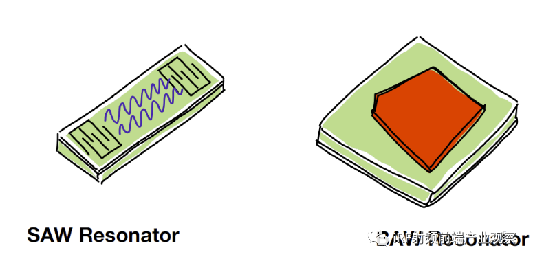
Several technologies compete together in the RF filter resonator space. Those technologies can be separated in 2 main categories:
· Those using surface acoustic waves or SAW
· Those using bulk acoustic waves or BAW
The basic physical principle behind is that acoustic waves have 2 main modes of propagation: within the bulk of the material and at the surface of the material.
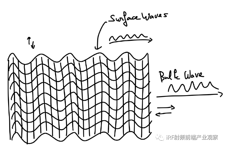
The speed of propagation of bulk waves is faster than the speed of propagation of surface waves. There are also a few other differences between those 2 modes of propagation that make SAW devices and BAW devices suited for different types of applications.
SAW RF resonators are cheaper than BAW RF resonators and are used for RF Filter applications for frequencies below 1.5 GHz. SAW RF filters have low Q-factor values and require temperature compensation method.
BAW RF resonators owing to the stable properties of thickness-extensional mode under temperature and stress bias have high Q-factor values and help to meet more stringent RF filter specifications. However, the resonator structure of these BAW devices is more complex to design to achieve the theoretical high Q-factor and hence more expensive. Let’s take a closer look.
What is a BAW resonator, and does it work?
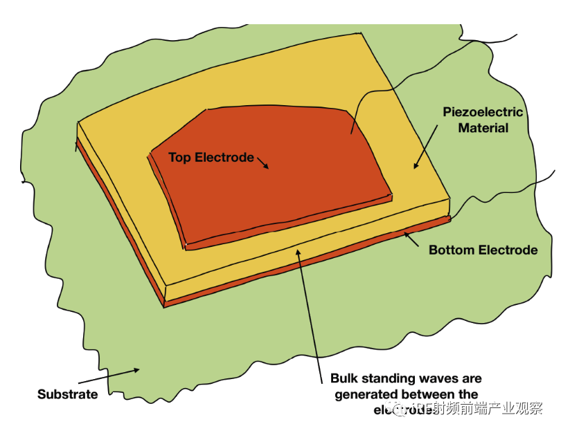
The basic principle is actually very simple. A BAW resonator is an electromechanical device composed of a piezoelectric material layer sandwiched in between 2 metallic electrodes.
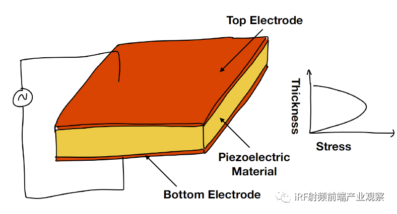
The charges accumulating on bottom electrode induce a deformation in the material generating an elastic or acoustic wave traveling into the piezoelectric material which gets reflected by the top electrode. Commonly used piezoelectric material are single crystalline Quartz, Aluminum nitride(AlN) and Zinc Oxide (ZnO).
When the thickness of the piezoelectric layer is exactly equal to 2 times the wavelength of the acoustic wave, the acoustic wave is excited and reflected which starts to “build on each other” to create a standing wave which oscillates at a very specific resonance frequency.
This frequency is the main subject of interest of designers of RF filter BAW resonator devices as it dictates the main characteristics of the pass-band filter.
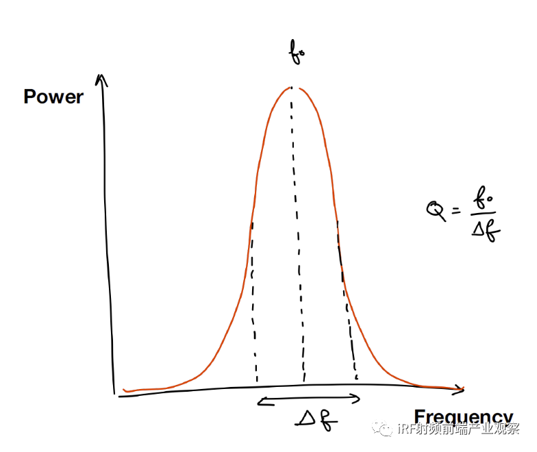
In theory, we would like the RF filter to have a well-defined resonant frequency, but in reality, RF filters always have some losses and their resonance frequency has a certain finite band, ?f, which is very important to know.
The quotient of the main resonant frequency over the ?f is called the Quality (Q)-factor and one of the jobs of the RF filter designers is to optimize the design to obtain the highest Q-factor.
Having a very good Q-factor means:
· Better and more accurate frequency filtering
· Less noise in the processed signal
· Lower insertion loss
All those parameters can be determined using simulation, which we will cover toward the end of the blog post.
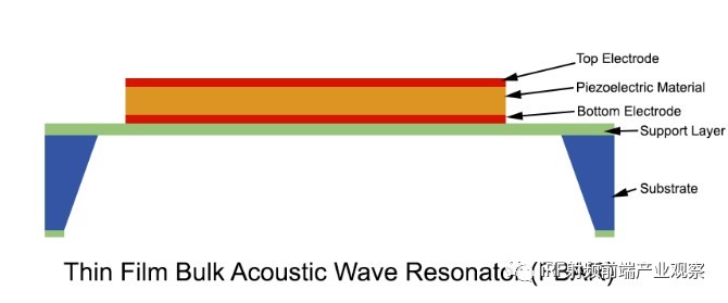
There are 2 popular ways to build BAW resonators:
· By mounting the BAW resonator on a cavity supported by side mounts. This is called a “Thin Film Bulk Acoustic Wave Resonator (TFBAR or FBAR).
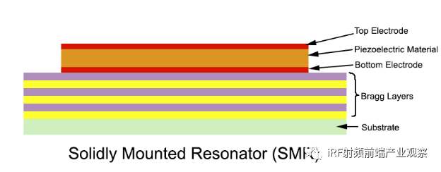
· By mounting the BAW resonator on alternate Bragg reflector layers of special material to prevent losses within the substrate material. This structure is called Solidly mounted resonator or SMR.
Each design type has its own design challenges. In an edge supported FBAR type structure, the shape of the electrodes becomes especially important as to avoid leakage of bulk waves at the boundary of the device.
A solidly mounted resonator (SMR) is a composite configuration where another dielectric material is placed below the main resonator structure to act as a supporting layer which can minimize the leakage of bulk acoustic waves inside the substrate. Those layers are called Bragg layers and their number and thickness is an important design parameter which requires a careful optimization.
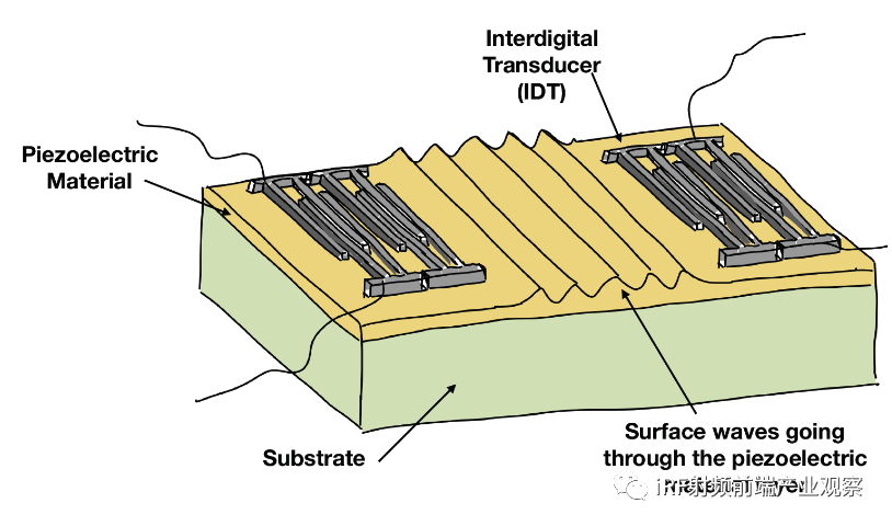
What about the SAW Filter?
Surface Acoustic Wave Filters use surface waves to filter a signal. The wave is sent by an Interdigital Device (IDT) which excites and make vibrate the piezoelectric layer substrate using the piezo electromechanical coupling property. The waves then travel to the second IDT where it is transcribed into another electrical signal. The piezoelectric substrate only vibrates at a specific natural frequency, so only waves close to that frequency can pass. Others are just filtered out.
Why use simulation to design BAW and SAW resonators?
When designing such an RF filter resonator:
· We want ultimately to change the thickness of the layers and the properties of the material in order to get the desired resonance frequency.
· We want to know as well how much stress will be generated both inside the device and near the mounting areas to ensure the design is structurally sound.
· We want to know what influence the temperature will have on the characteristics of the device.
· We want to know how the structural damping of the material will affect the performance and calculate the loss of energy.
· We want to calculate the impedance of the device and calculate the Q-factor as a function of the operation frequencies.
All of those wanted characteristics and design parameters can be obtained from a digital prototype created in the OnScale software, which eliminates the need for expensive and time-consuming physical prototypes.
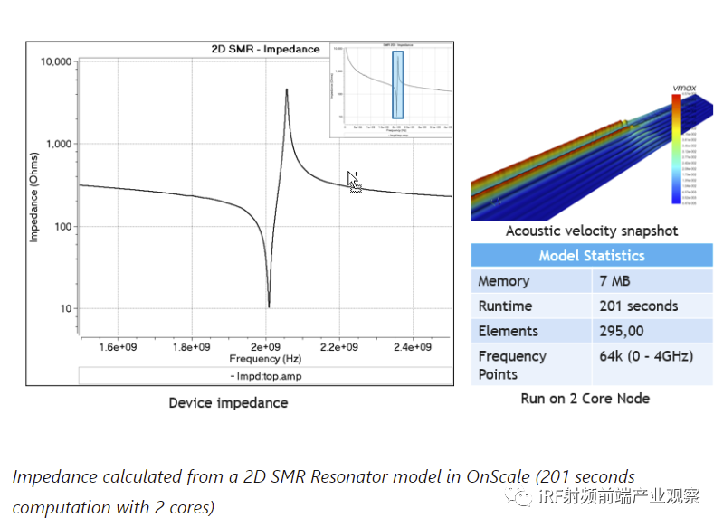
OnScale can efficiently simulate devices which couple piezoelectric material, acoustic waves, and mechanical behavior. For example, a 2D SMR resonator model takes around 3 min 35 sec to run.
Impedance calculated from a 2D SMR Resonator model in OnScale (201 seconds computation with 2 cores)
How to simulate SAW and BAW resonators with OnScale
The simulation process of an RF resonator consists of the following steps:
· Building a 2D or 3D model in OnScale(or importing it from a CAD file or MATLAB®)
· Assigning the material properties using the material database (showcasing all the piezo material characteristics) available in OnScale.
· Defining the electrodes and the type of time-distribution of the voltage to be applied.
· Defining the analysis time and the output data.
· Running the simulation locally (small models) or on the cloud (big models) directly from the software without having to involve the IT department.
· Postprocess the data to obtain the wanted KPIs (impedance, Q coefficient).
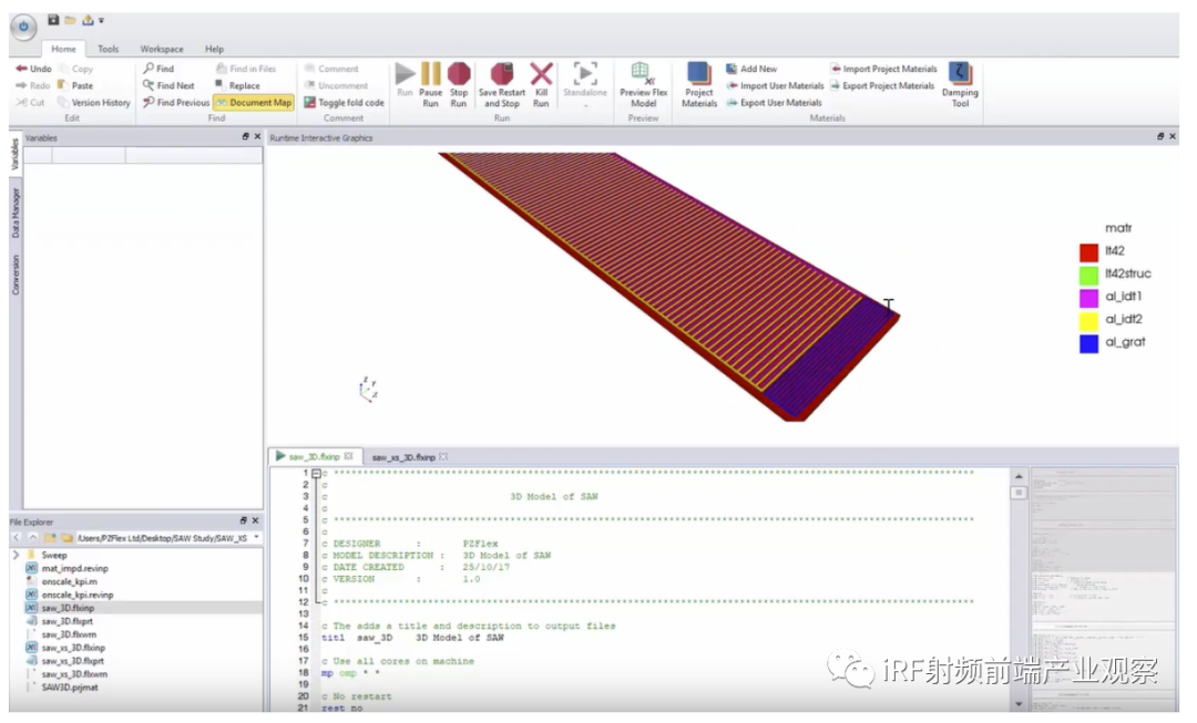
Full 3D SAW Resonator Simulation in OnScale
致谢
全文引用自onscale。请点击访问原文。版权归原作者所有。