私有网络模式
1. 登录 云防火墙控制台,在左侧导航栏中,选择防火墙开关 > VPC 间开关。
2. 在 VPC 间开关页面,单击防火墙实例,进入到防火墙实例页面,单击创建防火墙。

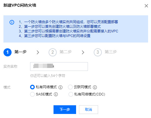
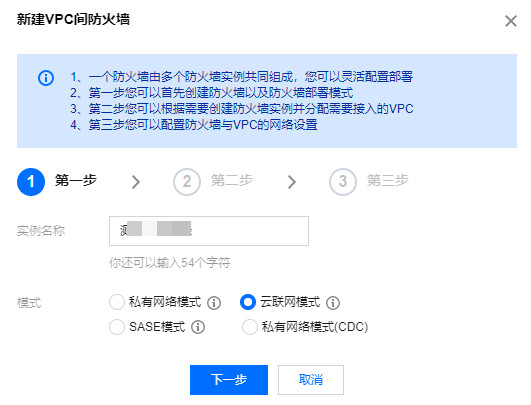
3. 在新建 VPC 间防火墙弹窗中,输入实例名称,选择私有网络模式,单击下一步。
参数说明:
实例名称:创建防火墙实例时自定义的名称。
模式:
私有网络模式:选择私有网络 VPC 接入防火墙,通过修改相关私有网络的路由表,来实现路由牵引。
云联网模式:选择云联网 CCN 接入防火墙(需要支持多路由表模式),通过修改云联网路由表,来实现路由牵引。
SASE 模式:功能限时内测中,如需使用请 提交工单。
私有网络模式(CDC):与私有网络模式一致,仅 CDC 环境可用。
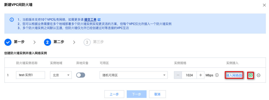
4. 填写防火墙实例名称和地域,配置灾备信息,设置防火墙实例带宽规格和接入网络,单击下一步。若实例数量不满足需求可单击右侧
参数说明:
地域:接入防护的 VPC 所属的地域。
异地灾备:VPC 间防火墙支持异地灾备,通过勾选来开启。
可用区:根据需求选择合适的可用区。
实例带宽:单实例目前最小1Gbps,最大20Gbps(控制台自行配置最大支持5Gbps,超过请 提交工单 评估),支持 升级扩容。如果不满足最大带宽可创建多个防火墙实例分流。但请注意,每个防火墙实例有其自身吞吐上限,多个防火墙实例请确认单实例在吞吐上限内。
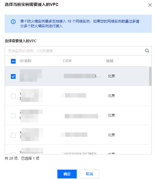
实例接入:单击接入网络,根据需要接入的 VPC 的地域分实例,选择所需 VPC,单击确定。
注意:
1个 VPC 仅可以接入1个实例。
防火墙无法进行基础网络的打通,接入网络之前,请确认 VPC 间已经创建对等链接/云联网,如果 VPC 之间没有建立连接,则接入不生效,不会有防火墙开关。
每个防火墙实例仅可接入同地域下的 VPC,每个实例最多可接入10个 VPC,支持同地域下创建多个防火墙实例。建议提前按照地域规划需要接入的 VPC,再创建防火墙实例并进行网络接入。
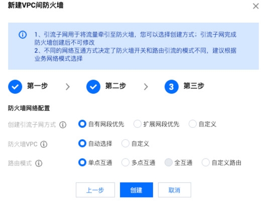
5. 配置创建引流子网方式、防火墙 VPC、路由模式,确认无误后单击创建即可。
说明:
完成配置,创建过程需要等待若干分钟,请耐心等待。
参数名称 | 说明 |
创建引流子网方式 | 云防火墙会在您所接入的VPC中新建24网段的子网,用于将流量牵引至防火墙,您可以选择不同的创建子网的方式。引流子网完成防火墙创建后不可修改。 自有网段优先:云防火墙会在您所选的 VPC 内自动选择空闲子网网段;当 VPC 内无子网配额时,我们会使用所选 VPC 的扩展网段。 扩展网段优先:云防火墙会优先使用空闲的 VPC 保留的扩展网段,该模式下不会占用所选 VPC 子网配额。其中,扩展网段是指私有网络中的辅助网段,详情可参见 私有网络-编辑 IPv4 CIDR。 自定义:您可以自定义供防火墙使用的子网网段,请注意必须为24网段;自定义网段必须属于当前 VPC 的 CIDR,例如192.168.0.0/24。 |
防火墙 VPC | 用来打通防火墙实例之间的网络通信,需要在所选 VPC 的所在地域各新建一个防火墙专用 VPC。 自动选择:防火墙会自动创建一个与接入 VPC 不冲突的20网段的 VPC。 自定义:请输入一个与规划网络不冲突的20段 VPC,例如192.168.1.0/20。 |
路由模式 | 防火墙开关的引流方案,不同的网络互通方式决定了防火墙开关和路由引流的模式不同,建议根据业务网络模式选择。 单点互通:适用于 VPC 数量较少,网络结构简单的拓扑;开关模式为 VPC 到 VPC,该模式下每个 VPC 之间的可达通路均会生成一个防火墙开关。 多点互通:适用于 VPC 数量较多,网络拓扑简单,如星型网络拓扑等;开关模式为单 VPC,该模式下 VPC 之间的访问会经过两个开关控制。 全互通:适用于 VPC 数量较多,网络拓扑复杂,如网状网络拓扑等;开关模式为全部 VPC,该模式下仅会有一个防火墙开关用于控制全部 VPC 路由。 自定义路由:您可以参考文档 自定义路由配置指引,在完成创建防火墙后自行配置路由,该模式下不会存在防火墙开关。 注意:选择多地域后仅支持自定义路由,具体路由模式是否可用请以控制台为准。 |
云联网模式
注意:
1. 登录 云防火墙控制台,在左侧导航栏中,选择防火墙开关 > VPC 间开关。
2. 在 VPC 间开关页面,单击防火墙实例,进入到防火墙实例页面,单击创建防火墙。
3. 在新建 VPC 间防火墙弹窗中,输入实例名称,选择云联网模式,单击下一步。
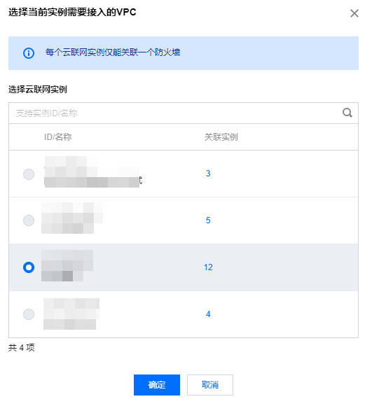
4. 单击点击选择,根据提示选择需要加入 VPC 防火墙的云联网实例,单击确定。
注意:
需要云联网实例支持多路由表模式,如未满足请先联系云联网开启多路由表功能。
云联网模式支持在指定地域创建 VPC 间防火墙。
云联网模式一个防火墙仅能绑定一个云联网实例。
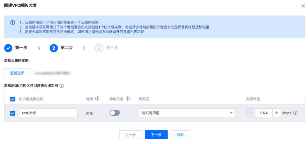
5. 选择完云联网实例后,下方会自动根据云联网接入的 VPC 生成可选地域,若勾选地域则会在所选地域创建1个防火墙实例。您可以配置防火墙实例名称、是否异地灾备以及实例带宽规格,单击下一步。
参数说明:
地域:接入防护的 VPC 所属的地域。
说明:
若仅勾选一个地域部署防火墙实例,所有开启了防火墙开关的 VPC 间流量都会经过该地域的防火墙实例,适合星形拓扑结构的业务网络。
若选择全部地域部署防火墙实例,开启了防火墙开关的 VPC 间流量都会经过本地域的防火墙实例,适合网状拓扑结构的业务网络。
选择多地域后仅支持自定义路由。
异地灾备:VPC 间防火墙支持异地灾备,通过勾选来开启。
可用区:根据需求选择合适的可用区。
注意:
每个防火墙实例有其自身吞吐上限,多个防火墙实例请确认单实例在吞吐上限内。
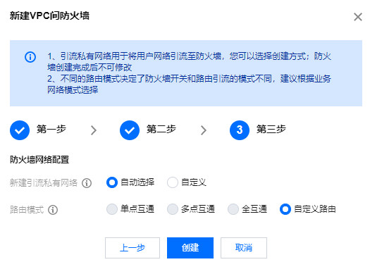
6. 配置新建引流私有网络、路由模式,确认无误后单击创建即可。
说明:
完成配置,创建过程需要等待若干分钟,请耐心等待。
参数名称 | 说明 |
新建引流私有网络 | 云防火墙会在您所选的云联网实例中新建20网段的私有网络,用于将流量牵引至防火墙,您可以选择不同的创建私有网络的方式。 自动选择:云防火墙会自动探测空闲的20段 VPC 网段,用于防火墙引流 自定义:您可以自定义供防火墙使用的私有网络网段,请注意必须为20网段。例如192.168.1.0/20 注意:
自2023年07月01日起,云联网服务将对网络实例和入流量处理进行收费,云防火墙需要在您接入的云联网实例中新建一个防火墙专用 VPC 用于引流,可能会产生一定费用,详情请参见 云联网商业化公告。 |
路由模式 | 防火墙开关的引流方案,不同的网络互通方式决定了防火墙开关和路由引流的模式不同,建议根据业务网络模式选择。 单点互通:适用于 VPC 数量较少,网络结构简单的拓扑;开关模式为 VPC 到 VPC,该模式下每个 VPC 之间的可达通路均会生成一个防火墙开关。 多点互通:适用于 VPC 数量较多,网络拓扑简单,如星型网络拓扑等;开关模式为单 VPC,该模式下 VPC 之间的访问会经过两个开关控制。 全互通:适用于 VPC 数量较多,网络拓扑复杂,如网状网络拓扑等;开关模式为全部 VPC,该模式下仅会有一个防火墙开关用于控制全部 VPC 路由。 自定义路由:您可以参考文档 自定义路由配置指引,在完成创建防火墙后自行配置路由,该模式下不会存在防火墙开关。 注意:选择多地域后仅支持自定义路由,具体路由模式是否可用请以控制台为准。 |
实例规格
VCP 间防火墙实例规格档位表。
说明:
VPC 间防火墙实例规格与内网间规则列表配额互相独立,不涉及计费逻辑,无法额外单独扩容,仅能通过提升实例规格实现。您每在控制台配置一条 ACL,我们会自动按照下发公式帮您转换为特定规则,并自动识别访问源和访问目的,下发到指定 VPC 间防火墙实例上。
下发公式:下发规则数 = 源地址个数 × 目的地址个数 × 端口个数 × 协议个数。
VPC 间防火墙实例规格决定了每个 VPC 间防火墙实例能承载的最大 ACL 规则数量,当 ACL 下发数量过多时可能会导致引擎出现不稳定的情况。
为了避免给您的业务造成影响,我们建议您根据每个实例的规格和下发规则数合理优化规则,减少冗余规则的占比,提升引擎稳定性。
规格档位 | 最低带宽/Mbps | 最高带宽/Mbps | 并发连接数/个 | 规则数配额/条 |
1 | 100 | 1,023 | 130,000 | 5,000(此档位不包含入侵防御功能) |
2 | 1,024 | 1,300 | 250,000 | 20,000 |
3 | 1,301 | 4,095 | 300,000 | 40,000 |
4 | 4,096 | 6,143 | 600,000 | 60,000 |
5 | 6,144 | 10,239 | 1,000,000 | 120,000 |
6 | 10,240 | 102,400 | 2,000,000 | 200,000 |


