
错误(10028):无法解决多个常量驱动程序和错误(10029):常量驱动程序
我是新的Verilog,并试图写一个交通灯代码,在LED灯变化后,一定的时间。我在编译的时候总是犯不同的错误。我试图通过更改排列或代码中的变量来修复它们,但仍然失败。
这是我写的代码,
module traffic_light(clk, reset, G1, Y1, R1, G2, Y2, R2);
input clk, reset;
output reg G1, Y1, R1, G2, Y2, R2;

// parameters for each light control
parameter GREEN = 3'b001,
             YELLOW = 3'b010,
             RED = 3'b100,
             LEFT_GREEN = 3'b101,   // assume both red and green will be turned on
             LEFT_YELLOW = 3'b110;  // assume both red and yellow will be turned on

// finite-state definition (Moore Type):
//                          ---------------------------
//                               NSlight          EWlight
//                          ---------------------------
parameter S0 = 3'd0, //  GREEN           RED
             S1 = 3'd1, //  YELLOW           RED
             S2 = 3'd2, // RED, GREEN        RED
             S3 = 3'd3, // RED, YELLOW       RED
             S4 = 3'd4, //      RED        GREEN
             S5 = 3'd5, //      RED       YELLOW
             S6 = 3'd6, //      RED     RED, GREEN
             S7 = 3'd7; //      RED     RED, YELLOW

// internal state variables
reg [2:0] state, next_state;

integer t1 = 19, t2 = 4;
integer count;

// buttons are appropriate for use as clock or reset inputs in a circuit
always @(posedge clk, negedge reset)
    if(reset == 'b0) // button pressed, when reset is active low
        begin
            next_state = S0;
            count = t1;
        end
    else
        state <= next_state;

always @(next_state)
    begin
        next_state = S0;
        count = t1;

        case(state)
            S0:
                if (count < 0) // load: if the count reaches below 0, reset
                    begin
                        count <= t2;
                        next_state <= S1;
                    end
                else // enable
                    begin
                        // down count
                        count <= count - 1;
                        // assign LEDs
                        G1 <= 1;
                        Y1 <= 0;
                        R1 <= 0;
                        G2 <= 0;
                        Y2 <= 0;
                        R2 <= 1;
                    end

            S1:
                if (count < 0)
                    begin
                        count <= t1;
                        next_state <= S2;
                    end
                else
                    begin
                        G1 <= 0;
                        Y1 <= 1;
                        R1 <= 0;
                        G2 <= 0;
                        Y2 <= 0;
                        R2 <= 1;
                        count <= count - 1;
                    end

            S2:
                if (count < 0)
                    begin
                        count <= t2;
                        next_state <= S3;
                    end
                else
                    begin
                        G1 <= 1;
                        Y1 <= 0;
                        R1 <= 1;
                        G2 <= 0;
                        Y2 <= 0;
                        R2 <= 1;
                        count <= count - 1;
                    end

            S3:
                if (count < 0)
                    begin
                        count <= t1;
                        next_state <= S4;
                    end
                else
                    begin
                        G1 <= 0;
                        Y1 <= 1;
                        R1 <= 1;
                        G2 <= 0;
                        Y2 <= 0;
                        R2 <= 1;
                        count <= count - 1;
                    end

            S4:
                if (count < 0)
                    begin
                        count <= t1;
                        next_state <= S5;
                    end
                else
                    begin
                        G1 <= 0;
                        Y1 <= 0;
                        R1 <= 1;
                        G2 <= 1;
                        Y2 <= 0;
                        R2 <= 0;
                        count <= count - 1;
                    end

            S5:
                if (count < 0)
                    begin
                        count <= t1;
                        next_state <= S6;
                    end
                else
                    begin
                        G1 <= 0;
                        Y1 <= 0;
                        R1 <= 1;
                        G2 <= 0;
                        Y2 <= 1;
                        R2 <= 0;
                        count <= count - 1;
                    end

            S6:
                if (count < 0)
                    begin
                        count <= t2;
                        next_state <= S7;
                    end
                else
                    begin
                        G1 <= 0;
                        Y1 <= 0;
                        R1 <= 1;
                        G2 <= 1;
                        Y2 <= 0;
                        R2 <= 1;
                        count <= count - 1;
                    end

            S7:
                if (count < 0)
                    begin
                        count <= t1;
                        next_state <= S0;
                    end
                else
                    begin
                        G1 <= 0;
                        Y1 <= 0;
                        R1 <= 1;
                        G2 <= 0;
                        Y2 <= 1;
                        R2 <= 1;
                        count <= count - 1;
                    end

        endcase
    end
endmodule
以下是从上述代码中生成的错误:
错误(10028):无法解析traffic_light.v(41)上的网络“traffic_light.v”的多个常量驱动程序
错误(10029):traffic_light.v上的恒定驱动程序(32)
错误(10028):无法解析traffic_light.v(41)上的网络“traffic_light.v”的多个常量驱动程序
错误(10028):无法解析traffic_light.v(41)上的网络“traffic_light.v”的多个常量驱动程序
错误(10028):无法解析traffic_light.v(41)上的网络“traffic_light.v”的多个常量驱动程序
错误(10028):无法解析traffic_light.v(41)上的网络“traffic_light.v”的多个常量驱动程序
错误(10028):无法解析traffic_light.v(41)上的网络“traffic_light.v”的多个常量驱动程序
错误(12152):无法详细说明用户层次结构"traffic_light:inst“
希望我能得到对这个问题的任何建议或解决方案。提前谢谢你。
经过几次搜索,我解决了这个问题。
错误(10028):无法解析网络的多个常量驱动程序。VHDL误差
具有Quartus素数的“多重恒定驱动程序”误差Verilog
这两个链接帮助解决了问题,问题是不能在两个不同的始终块中分配一个变量。下面的代码是固定的。
module traffic_light(clk, reset, G1, Y1, R1, G2, Y2, R2, time_);
input clk, reset;
output reg G1, Y1, R1, G2, Y2, R2;
output reg [4:0] time_; // added, it displays the remaining time

// parameters for each light control
parameter GREEN = 3'b001,
             YELLOW = 3'b010,
             RED = 3'b100,
             LEFT_GREEN = 3'b101,   // assume both red and green will be turned on
             LEFT_YELLOW = 3'b110;  // assume both red and yellow will be turned on

// finite-state definition (Moore Type):
//                          ---------------------------
//                               NSlight          EWlight
//                          ---------------------------
parameter S0 = 3'd0, //  GREEN           RED
             S1 = 3'd1, //  YELLOW           RED
             S2 = 3'd2, // RED, GREEN        RED
             S3 = 3'd3, // RED, YELLOW       RED
             S4 = 3'd4, //      RED        GREEN
             S5 = 3'd5, //      RED       YELLOW
             S6 = 3'd6, //      RED     RED, GREEN
             S7 = 3'd7; //      RED     RED, YELLOW

// internal state variables and time settings
reg [2:0] state, next_state;
integer t1 = 19, t2 = 4;
reg count; // changed to count only

always @(posedge clk)
    if(reset == 0) // button pressed, when reset is active low
        begin
            state <= S0;
            time_ <= t1;
        end
    else
        begin
            state <= next_state;
            time_ <= count;
        end

always @(*) // changed according to advice in the comment
    case(state)
        S0:     if (count < 0) // load: if the count reaches below 0, reset
                    begin
                        count <= t2;
                        next_state <= S1;
                    end
                else // enable
                    begin
                        // down count
                        count <= count - 1;
                        // assign LEDs
                        G1 <= 1;
                        Y1 <= 0;
                        R1 <= 0;
                        G2 <= 0;
                        Y2 <= 0;
                        R2 <= 1;
                    end

        S1:     if (count < 0)
                    begin
                        count <= t1;
                        next_state <= S2;
                    end
                else
                    begin
                        G1 <= 0;
                        Y1 <= 1;
                        R1 <= 0;
                        G2 <= 0;
                        Y2 <= 0;
                        R2 <= 1;
                        count <= count - 1;
                    end


        S2:     if (count < 0)
                    begin
                        count <= t2;
                        next_state <= S3;
                    end
                else
                    begin
                        G1 <= 1;
                        Y1 <= 0;
                        R1 <= 1;
                        G2 <= 0;
                        Y2 <= 0;
                        R2 <= 1;
                        count <= count - 1;
                    end

        S3: if (count < 0)
                    begin
                        count <= t1;
                        next_state <= S4;
                    end
                else
                    begin
                        G1 <= 0;
                        Y1 <= 1;
                        R1 <= 1;
                        G2 <= 0;
                        Y2 <= 0;
                        R2 <= 1;
                        count <= count - 1;
                    end

        S4:     if (count < 0)
                    begin
                        count <= t2;
                        next_state <= S5;
                    end
                else
                    begin
                        G1 <= 0;
                        Y1 <= 0;
                        R1 <= 1;
                        G2 <= 1;
                        Y2 <= 0;
                        R2 <= 0;
                        count <= count - 1;
                    end

        S5: if (count < 0)
                    begin
                        count <= t1;
                        next_state <= S6;
                    end
                else
                    begin
                        G1 <= 0;
                        Y1 <= 0;
                        R1 <= 1;
                        G2 <= 0;
                        Y2 <= 1;
                        R2 <= 0;
                        count <= count - 1;
                    end

        S6: if (count < 0)
                    begin
                        count <= t2;
                        next_state <= S7;
                    end
                else
                    begin
                        G1 <= 0;
                        Y1 <= 0;
                        R1 <= 1;
                        G2 <= 1;
                        Y2 <= 0;
                        R2 <= 1;
                        count <= count - 1;
                    end

        S7: if (count < 0)
                    begin
                        count <= t1;
                        next_state <= S0;
                    end
                else
                    begin
                        G1 <= 0;
                        Y1 <= 0;
                        R1 <= 1;
                        G2 <= 0;
                        Y2 <= 1;
                        R2 <= 1;
                        count <= count - 1;
                    end

        default:
            begin
                next_state <= S0;
                count <= t1;
            end

    endcase
endmodule回答 1
Stack Overflow用户
发布于 2022-11-03 08:51:01
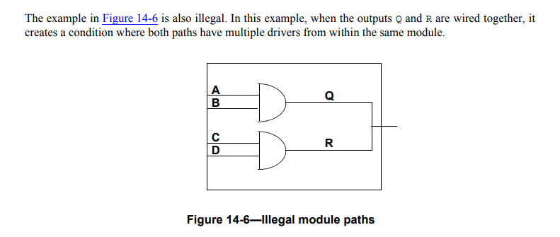
在这两个进程中都分配了next_state,这会带来麻烦。我们可以在Verilog标准中找到它的实际描述。部分14.5驱动有线逻辑
模块路径输出网在模块内不得有多个驱动程序。因此,模块路径输出不允许有线逻辑。
它还提供了一个例子:
https://stackoverflow.com/questions/74298755
复制相似问题
腾讯云开发者
