
渲染填充表面时更好地显示BW显示的阴影
序言
我终于解决了AT32UC3xxxxx和SSD1306 OLED I2C显示器之间的HW不兼容问题(两者都有HW错误使它们不兼容),允许我在400 frame (~26.6ms /帧)的情况下使用HW I2C。因此,我决定为这个LCD重写我的旧驱动程序,以利用新的速度,增加填充的表面(三角形,四边形),而不是仅仅是线条和图案线(我已经实现了)。
问题是显示是128 x64像素,但是没有颜色或灰色,只有BW开/关。
因此,例如,为了渲染旋转立方体,我需要以某种方式区分曲面。我在考虑随机填充模式,表面填充到一定百分比,而不是颜色。
在这里,我的当前代码(完整的库,但没有but,它应该正常工作):
LCD_SSD1306_I2C.h
//------------------------------------------------------------------------------------------
//--- SSD1306 I2C OLED LCD driver ver 2.000 ------------------------------------------------
//------------------------------------------------------------------------------------------
#ifndef _LCD_SSD1306_I2C_h
#define _LCD_SSD1306_I2C_h
//------------------------------------------------------------------------------------------
#define SSD1306_SETCONTRAST 0x81
#define SSD1306_DISPLAYALLON_RESUME 0xA4
#define SSD1306_DISPLAYALLON 0xA5
#define SSD1306_NORMALDISPLAY 0xA6
#define SSD1306_INVERTDISPLAY 0xA7
#define SSD1306_DISPLAYOFF 0xAE
#define SSD1306_DISPLAYON 0xAF
#define SSD1306_SETDISPLAYOFFSET 0xD3
#define SSD1306_SETCOMPINS 0xDA
#define SSD1306_SETVCOMDETECT 0xDB
#define SSD1306_SETDISPLAYCLOCKDIV 0xD5
#define SSD1306_SETPRECHARGE 0xD9
#define SSD1306_SETMULTIPLEX 0xA8
#define SSD1306_SETLOWCOLUMN 0x00
#define SSD1306_SETHIGHCOLUMN 0x10
#define SSD1306_SETSTARTLINE 0x40
#define SSD1306_MEMORYMODE 0x20
#define SSD1306_COLUMNADDR 0x21
#define SSD1306_PAGEADDR   0x22
#define SSD1306_COMSCANINC 0xC0
#define SSD1306_COMSCANDEC 0xC8
#define SSD1306_SEGREMAP 0xA0
#define SSD1306_CHARGEPUMP 0x8D
#define SSD1306_SWITCHCAPVCC 0x2
// Scrolling #defines
#define SSD1306_ACTIVATE_SCROLL 0x2F
#define SSD1306_DEACTIVATE_SCROLL 0x2E
#define SSD1306_SET_VERTICAL_SCROLL_AREA 0xA3
#define SSD1306_RIGHT_HORIZONTAL_SCROLL 0x26
#define SSD1306_LEFT_HORIZONTAL_SCROLL 0x27
#define SSD1306_VERTICAL_AND_RIGHT_HORIZONTAL_SCROLL 0x29
#define SSD1306_VERTICAL_AND_LEFT_HORIZONTAL_SCROLL 0x2A
//------------------------------------------------------------------------------------------
//#define I2C_send(adr,buf,siz){}
//------------------------------------------------------------------------------------------
#ifndef _brv8_tab
#define _brv8_tab
static const U8 brv8[256] =     // 8 bit bit reversal
    {
    0,128,64,192,32,160,96,224,16,144,80,208,48,176,112,240,8,136,72,200,40,168,104,232,24,152,
    88,216,56,184,120,248,4,132,68,196,36,164,100,228,20,148,84,212,52,180,116,244,12,140,76,204,
    44,172,108,236,28,156,92,220,60,188,124,252,2,130,66,194,34,162,98,226,18,146,82,210,50,178,
    114,242,10,138,74,202,42,170,106,234,26,154,90,218,58,186,122,250,6,134,70,198,38,166,102,230,
    22,150,86,214,54,182,118,246,14,142,78,206,46,174,110,238,30,158,94,222,62,190,126,254,1,129,
    65,193,33,161,97,225,17,145,81,209,49,177,113,241,9,137,73,201,41,169,105,233,25,153,89,217,57,
    185,121,249,5,133,69,197,37,165,101,229,21,149,85,213,53,181,117,245,13,141,77,205,45,173,109,
    237,29,157,93,221,61,189,125,253,3,131,67,195,35,163,99,227,19,147,83,211,51,179,115,243,11,139,
    75,203,43,171,107,235,27,155,91,219,59,187,123,251,7,135,71,199,39,167,103,231,23,151,87,215,55,
    183,119,247,15,143,79,207,47,175,111,239,31,159,95,223,63,191,127,255
    };
#endif
//------------------------------------------------------------------------------------------
class LCD_SSD1306_I2C           // max 96 lines
    {
public:
    // screen
    int adr;                    // I2C adr
    int xs,ys,sz;               // resoluiton
    U8 _scr[((128*96)>>3)+1];   // screen buffer
    U8 *scr;
    U8 *pyx[96];                // scan lines
    // pattern
    U32 pat,pat_m,pat_b;        // binary pattern,max used bit mask,actual bit mask
    // filling
    U32 seed;
    int bufl[96];
    int bufr[96];

    // system api
    void init(int _adr,int _xs,int _ys);                    // initialize LCD: I2C_adr,xs,ys
    void _command(U8 cmd);                                  // *internal* do not cal it (sends command to LCD over I2C)
    void rfsscr();                                          // copy actual screen buffer to LCD (by I2C)
    // gfx rendering col = <0,1>
    void clrscr();                                          // clear screen buffer
    void rotate(int ang);                                   // rotate 180 deg
    void pixel(int x,int y,bool col);                       // set/res pixel
    bool pixel(int x,int y);                                // get pixel
    void line(int x0,int y0,int x1,int y1,bool col);        // line
    void triangle(int x0,int y0,int x1,int y1,int x2,int y2,bool col);// triangle
    void quad(int x0,int y0,int x1,int y1,int x2,int y2,int x3,int y3,bool col);
    void rect(int x0,int y0,int x1,int y1,bool col);        // rectangle using diagonal points
    // patern rendering
    void pat_set(char *s);                                  // set binary pattern from bianry number string MSB renders first
    void pat_beg();                                         // set pattern state to start of pattern
    void pat_line(int x0,int y0,int x1,int y1,bool col);
    void pat_triangle(int x0,int y0,int x1,int y1,int x2,int y2,bool col);
    void pat_quad(int x0,int y0,int x1,int y1,int x2,int y2,int x3,int y3,bool col);
    void pat_rect(int x0,int y0,int x1,int y1,bool col);
    // filled polygons col = <0,255>
    void _fill_line(int x0,int y0,int x1,int y1);           // *internal* do not call it (render line into bufl/bufr)
    void _fill_seed();                                      // *internal* do not call it (reset seed)
    U8   _fill_rand();                                      // *internal* do not call it (get pseudo random number)
    void fill_triangle(int x0,int y0,int x1,int y1,int x2,int y2,U8 col);
    void fill_quad(int x0,int y0,int x1,int y1,int x2,int y2,int x3,int y3,U8 col);
    // text rendering
    void prnchr(int x,int y,char c);                        // render char at x,y (y is rounded to multiple of 8)
    void prntxt(int x,int y,const char *txt);               // render text at x,y (y is rounded to multiple of 8)
    };
//------------------------------------------------------------------------------------------
void LCD_SSD1306_I2C::_command(U8 cmd)
    {
    U8 buf[2]=
        {
        0x00,       // 0x40 data/command
        cmd,
        };
    I2C_send(adr,buf,2);
    }
//------------------------------------------------------------------------------------------
void LCD_SSD1306_I2C::init(int _adr,int _xs,int _ys)
    {
    int y;
    adr=_adr;
    xs=_xs;
    ys=_ys;
    sz=xs*(ys>>3);
    const bool _external_Vcc=false;
    // VRAM buffer
    scr=_scr+1;                                         // skip first Byte (VRAM/command selection)
    for (y=0;y<ys;y++) pyx[y]=scr+((y>>3)*xs);          // scanlines for fast direct pixel access
    clrscr();
    // Init sequence
    U8 comPins = 0x02;
    U8 contrast = 0x8F;
         if((xs == 128) && (ys == 32)) { comPins = 0x02; contrast = 0x8F; }
    else if((xs == 128) && (ys == 64)) { comPins = 0x12; contrast = (_external_Vcc) ? 0x9F : 0xCF; }
    else if((xs ==  96) && (ys == 16)) { comPins = 0x02; contrast = (_external_Vcc) ? 0x10 : 0xAF; }
    else {} // Other screens
    static U8 init0[27]=
        {
        0x00,                                           // commands
        SSD1306_DISPLAYOFF,                             // 0xAE
        SSD1306_SETDISPLAYCLOCKDIV,0x80,                // 0xD5
        SSD1306_SETMULTIPLEX,ys-1,                      // 0xA8
        SSD1306_SETDISPLAYOFFSET,0x00,                  // 0xD3 no offset
        SSD1306_SETSTARTLINE | 0x0,                     // line 0
        SSD1306_CHARGEPUMP,(_external_Vcc)?0x10:0x14,   // 0x8D
        SSD1306_MEMORYMODE,0x00,                        // 0x20 horizontal (scanlines)
        SSD1306_SEGREMAP | 0x1,
        SSD1306_COMSCANDEC,
        SSD1306_SETCOMPINS,comPins,
        SSD1306_SETCONTRAST,contrast,
        SSD1306_SETPRECHARGE,(_external_Vcc)?0x22:0xF1, // 0xd9
        SSD1306_SETVCOMDETECT,0x40,                     // 0xDB
        SSD1306_DISPLAYALLON_RESUME,                    // 0xA4
        SSD1306_NORMALDISPLAY,                          // 0xA6
        SSD1306_DEACTIVATE_SCROLL,
        SSD1306_DISPLAYON,                              // Main screen turn on
        };
    I2C_send(adr,init0,sizeof(init0));
    // init default pattern
    pat_set("111100100");
    // clear filling buffers
    for (y=0;y<96;y++)
        {
        bufl[y]=-1;
        bufr[y]=-1;
        }
    }
//------------------------------------------------------------------------------------------
void LCD_SSD1306_I2C::clrscr()
    {
    for (int a=0;a<sz;a++) scr[a]=0x00;
    }
//------------------------------------------------------------------------------------------
void LCD_SSD1306_I2C::rotate(int ang)
    {
    U8 a0,a1;
    int x0,y0,x1,y1;
    if (ang==180)
     for (y0=0,y1=ys-8;y0<y1;y0+=8,y1-=8)
      for (x0=0,x1=xs-1;x0<xs;x0++,x1--)
          {
          a0=brv8[pyx[y0][x0]];
          a1=brv8[pyx[y1][x1]];
          pyx[y0][x0]=a1;
          pyx[y1][x1]=a0;
          }
    }
//------------------------------------------------------------------------------------------
void LCD_SSD1306_I2C::rfsscr()
    {
    static const U8 init1[] =
        {
        0x00,                           // commands
        SSD1306_MEMORYMODE,0,           // horizontal addresing mode
        SSD1306_COLUMNADDR,0,xs-1,      // Column start/end address (0/127 reset)
        SSD1306_PAGEADDR,0,(ys>>3)-1,   // Page start/end address (0 reset)
        };
    I2C_send(adr,(U8*)init1,sizeof(init1));

    _scr[0]=0x40;                       // 0x40 VRAM
    // SW I2C can pass whole VRAM in single packet
//  I2C_send(adr,_scr,sz+1);

    // HW I2C must use packets up to 255 bytes so 128+1 (as TWIM0 on UC3 has 8 bit counter)
    int i,n=128; U8 *p=_scr,a;
    for (i=0;i<sz;i+=n){ a=p[0]; p[0]=0x40; I2C_send(adr,p,n+1); p[0]=a; p+=n; }
    }
//------------------------------------------------------------------------------------------
void LCD_SSD1306_I2C::pixel(int x, int y,bool col)
    {
    // clip to screen
    if ((x<0)||(x>=xs)||(y<0)||(y>=ys)) return;
    // add or remove bit
    if (col) pyx[y][x] |= (1<<(y&7));
    else     pyx[y][x] &= (255)^(1<<(y&7));
    }
//------------------------------------------------------------------------------------------
bool LCD_SSD1306_I2C::pixel(int x, int y)
    {
    // clip to screen
    if ((x<0)||(x>=xs)||(y<0)||(y>=ys)) return false;
    // get bit
    return ((pyx[y][x]>>(y&7))&1);
    }
//------------------------------------------------------------------------------------------
void LCD_SSD1306_I2C::line(int x0,int y0,int x1,int y1,bool col)
    {
    int i,n,cx,cy,sx,sy;
    // line DDA parameters
    x1-=x0; sx=0; if (x1>0) sx=+1; if (x1<0) { sx=-1; x1=-x1; } if (x1) x1++;           n=x1;
    y1-=y0; sy=0; if (y1>0) sy=+1; if (y1<0) { sy=-1; y1=-y1; } if (y1) y1++; if (n<y1) n=y1;
    // single pixel (not a line)
    if (!n){ pixel(x0,y0,col); return; }
    // ND DDA algo i is parameter
    for (cx=cy=n,i=0;i<n;i++)
        {
        pixel(x0,y0,col);
        cx-=x1; if (cx<=0){ cx+=n; x0+=sx; }
        cy-=y1; if (cy<=0){ cy+=n; y0+=sy; }
        }
    }
//------------------------------------------------------------------------------------------
void LCD_SSD1306_I2C::pat_line(int x0,int y0,int x1,int y1,bool col)
    {
    bool ccc;
    int i,n,cx,cy,sx,sy;
    // line DDA parameters
    x1-=x0; sx=0; if (x1>0) sx=+1; if (x1<0) { sx=-1; x1=-x1; } if (x1) x1++;           n=x1;
    y1-=y0; sy=0; if (y1>0) sy=+1; if (y1<0) { sy=-1; y1=-y1; } if (y1) y1++; if (n<y1) n=y1;
    // single pixel (not a line)
    if (!n){ pixel(x0,y0,col); return; }
    // ND DDA algo i is parameter
    for (cx=cy=n,i=0;i<n;i++)
        {
        ccc=(pat&pat_b); ccc^=(!col);
        pat_b>>=1; if (!pat_b) pat_b=pat_m;
        pixel(x0,y0,ccc);
        cx-=x1; if (cx<=0){ cx+=n; x0+=sx; }
        cy-=y1; if (cy<=0){ cy+=n; y0+=sy; }
        }
    }
//------------------------------------------------------------------------------------------
void LCD_SSD1306_I2C::_fill_line(int x0,int y0,int x1,int y1)
    {
    int i,n,cx,cy,sx,sy,*buf;
    // line DDA parameters
    x1-=x0; sx=0; if (x1>0) sx=+1; if (x1<0) { sx=-1; x1=-x1; } if (x1) x1++;           n=x1;
    y1-=y0; sy=0; if (y1>0) sy=+1; if (y1<0) { sy=-1; y1=-y1; } if (y1) y1++; if (n<y1) n=y1;
    // single pixel (not a line)
    if (!n)
        {
        if ((y0>=0)&&(y0<ys))
            {
            bufl[y0]=x0;
            bufr[y0]=x0;
            }
        return;
        }
    // target buffer depend on y direction
    if (sy>0) buf=bufl; else buf=bufr;
    // ND DDA algo i is parameter
    for (cx=cy=n,i=0;i<n;i++)
        {
        if ((y0>=0)&&(y0<ys)) buf[y0]=x0;
        cx-=x1; if (cx<=0){ cx+=n; x0+=sx; }
        cy-=y1; if (cy<=0){ cy+=n; y0+=sy; }
        }
    }
//------------------------------------------------------------------------------------------
void LCD_SSD1306_I2C::_fill_seed()
    {
    seed=0x017A357E1;
//  RandSeed=0x017A357E1;
    }
//------------------------------------------------------------------------------------------
U8 LCD_SSD1306_I2C::_fill_rand()
    {
    U32 a,b,c;
    a= seed     &0x0FFFF;
    b=(seed>>16)&0x0FFFF;
    seed<<=11;
    seed^=(a<<16);
    seed&=0x0FFFF0000;
    seed|=b+17;
    return seed&255;
//  return Random(256);
    }
//------------------------------------------------------------------------------------------
void LCD_SSD1306_I2C::triangle(int x0,int y0,int x1,int y1,int x2,int y2,bool col)
    {
    line(x0,y0,x1,y1,col);
    line(x1,y1,x2,y2,col);
    line(x2,y2,x0,y0,col);
    }
//------------------------------------------------------------------------------------------
void LCD_SSD1306_I2C::pat_triangle(int x0,int y0,int x1,int y1,int x2,int y2,bool col)
    {
    pat_line(x0,y0,x1,y1,col);
    pat_line(x1,y1,x2,y2,col);
    pat_line(x2,y2,x0,y0,col);
    }
//------------------------------------------------------------------------------------------
void LCD_SSD1306_I2C::fill_triangle(int x0,int y0,int x1,int y1,int x2,int y2,U8 col)
    {
    int x,y,X0,X1,Y0,Y1;
    // y range to render
    Y0=Y1=y0;
    if (Y0>y1) Y0=y1;
    if (Y1<y1) Y1=y1;
    if (Y0>y2) Y0=y2;
    if (Y1<y2) Y1=y2;
    // clip to screen in y axis
    if ((Y1<0)||(Y0>=ys)) return;
    if (Y0<  0) Y0=   0;
    if (Y1>=ys) Y1=ys-1;
    // clear buffers
    for (y=Y0;y<=Y1;y++)
        {
        bufl[y]=xs;
        bufr[y]=-1;
        }
    // render circumference
    _fill_line(x0,y0,x1,y1);
    _fill_line(x1,y1,x2,y2);
    _fill_line(x2,y2,x0,y0);
    // fill horizontal lines
    _fill_seed();
    for (y=Y0;y<=Y1;y++)
        {
        // x range to render
        X0=bufl[y];
        X1=bufr[y];
        if (X0>X1){ x=X0; X0=X1; X1=x; }
        // clip to screen in y axis
        if ((X1<0)||(X0>=xs)) continue;
        if (X0<  0) X0=   0;
        if (X1>=xs) X1=xs-1;
             if (col==  0) for (x=X0;x<=X1;x++) pixel(x,y,0);
        else if (col==255) for (x=X0;x<=X1;x++) pixel(x,y,1);
        else for (x=X0;x<=X1;x++) pixel(x,y,(_fill_rand()<=col));
        }
    }
//------------------------------------------------------------------------------------------
void LCD_SSD1306_I2C::quad(int x0,int y0,int x1,int y1,int x2,int y2,int x3,int y3,bool col)
    {
    line(x0,y0,x1,y1,col);
    line(x1,y1,x2,y2,col);
    line(x2,y2,x3,y3,col);
    line(x3,y3,x0,y0,col);
    }
//------------------------------------------------------------------------------------------
void LCD_SSD1306_I2C::pat_quad(int x0,int y0,int x1,int y1,int x2,int y2,int x3,int y3,bool col)
    {
    pat_line(x0,y0,x1,y1,col);
    pat_line(x1,y1,x2,y2,col);
    pat_line(x2,y2,x3,y3,col);
    pat_line(x3,y3,x0,y0,col);
    }
//------------------------------------------------------------------------------------------
void LCD_SSD1306_I2C::fill_quad(int x0,int y0,int x1,int y1,int x2,int y2,int x3,int y3,U8 col)
    {
    int x,y,X0,X1,Y0,Y1;
    // y range to render
    Y0=Y1=y0;
    if (Y0>y1) Y0=y1;
    if (Y1<y1) Y1=y1;
    if (Y0>y2) Y0=y2;
    if (Y1<y2) Y1=y2;
    if (Y0>y3) Y0=y3;
    if (Y1<y3) Y1=y3;
    // clip to screen in y axis
    if ((Y1<0)||(Y0>=ys)) return;
    if (Y0<  0) Y0=   0;
    if (Y1>=ys) Y1=ys-1;
    // clear buffers
    for (y=Y0;y<=Y1;y++)
        {
        bufl[y]=xs;
        bufr[y]=-1;
        }
    // render circumference
    _fill_line(x0,y0,x1,y1);
    _fill_line(x1,y1,x2,y2);
    _fill_line(x2,y2,x3,y3);
    _fill_line(x3,y3,x0,y0);
    // fill horizontal lines
    _fill_seed();
    for (y=Y0;y<=Y1;y++)
        {
        // x range to render
        X0=bufl[y];
        X1=bufr[y];
        if (X0>X1){ x=X0; X0=X1; X1=x; }
        // clip to screen in y axis
        if ((X1<0)||(X0>=xs)) continue;
        if (X0<  0) X0=   0;
        if (X1>=xs) X1=xs-1;
             if (col==  0) for (x=X0;x<=X1;x++) pixel(x,y,0);
        else if (col==255) for (x=X0;x<=X1;x++) pixel(x,y,1);
        else for (x=X0;x<=X1;x++) pixel(x,y,(_fill_rand()<=col));
        }
    }
//------------------------------------------------------------------------------------------
void LCD_SSD1306_I2C::rect(int x0,int y0,int x1,int y1,bool col)
    {
    line(x0,y0,x1,y0,col);
    line(x1,y0,x1,y1,col);
    line(x1,y1,x0,y1,col);
    line(x0,y1,x0,y0,col);
    }
//------------------------------------------------------------------------------------------
void LCD_SSD1306_I2C::pat_rect(int x0,int y0,int x1,int y1,bool col)
    {
    pat_line(x0,y0,x1,y0,col);
    pat_line(x1,y0,x1,y1,col);
    pat_line(x1,y1,x0,y1,col);
    pat_line(x0,y1,x0,y0,col);
    }
//------------------------------------------------------------------------------------------
void LCD_SSD1306_I2C::prnchr(int x,int y,char c)
    {
    y&=0xFFFFFFF8;  // multiple of 8
    if ((y<0)||(y>ys-8)) return;
    int i,a;
    a=c; a<<=3;
    for (i=0;i<8;i++,x++,a++)
     if ((x>=0)&&(x<xs))
      pyx[y][x]=font[a];
    }
//------------------------------------------------------------------------------------------
void LCD_SSD1306_I2C::prntxt(int x,int y,const char *txt)
    {
    for (;*txt;txt++,x+=8) prnchr(x,y,*txt);
    }
//------------------------------------------------------------------------------------------
void LCD_SSD1306_I2C::pat_set(char *s)
    {
    int i=1;
    pat=0;
    if (s!=NULL)
     for (i=0;(*s)&&(i<32);s++,i++)
        {
        pat<<=1;
        if (*s=='1') pat|=1;
        }
    if (!i) i=1;
    pat_m=1<<(i-1);
    pat_beg();
    }
//------------------------------------------------------------------------------------------
void LCD_SSD1306_I2C::pat_beg()
    {
    pat_b=pat_m;
    }
//------------------------------------------------------------------------------------------
#undef I2C_send
//------------------------------------------------------------------------------------------
#endif
//------------------------------------------------------------------------------------------
它是为AVR32 studio 2.7编写的,例如在没有U8/U16/U32的平台上,使用无符号int,而不是相同(或更大)的位宽。
代码没有经过优化,而且是故意以它的方式编写的(不是为了速度,我在讲课中也使用了这个方法,这样学生就可以掌握我正在做的事情)。
当我使用2D填充四角体使用这一技术呈现旋转立方体(在PC上win32 VCL测试应用程序上)时,
//---------------------------------------------------------------------------
#include <vcl.h>
#include <math.h>
#pragma hdrstop
#include "win_main.h"
//---------------------------------------------------------------------------
#pragma package(smart_init)
#pragma resource "*.dfm"
TMain *Main;
const int sz=4;         // LCD pixel size
int xs,ys;              // LCD resolution * sz
int *psz;               // screen pixel to LCD pixel
Graphics::TBitmap *bmp; // screen buffer
//---------------------------------------------------------------------------
typedef BYTE U8; // here use data types you got like unsigned __int8_t ...
typedef WORD U16;
typedef DWORD U32;
void I2C_send(int adr,U8 *buf,int siz){}
//#include "font_8x8.h"  // font file
static U8 font[256<<3]; // empty font instead (no printing used)
#include "LCD_SSD1306_I2C.h"
LCD_SSD1306_I2C lcd;
//---------------------------------------------------------------------------
const float cube_pos[]=
    {
//  x    y    z     //ix
    -1.0,+1.0,-1.0, //0
    +1.0,+1.0,-1.0, //1
    +1.0,-1.0,-1.0, //2
    -1.0,-1.0,-1.0, //3

    -1.0,-1.0,+1.0, //4
    +1.0,-1.0,+1.0, //5
    +1.0,+1.0,+1.0, //6
    -1.0,+1.0,+1.0, //7

    -1.0,-1.0,-1.0, //3
    +1.0,-1.0,-1.0, //2
    +1.0,-1.0,+1.0, //5
    -1.0,-1.0,+1.0, //4

    +1.0,-1.0,-1.0, //2
    +1.0,+1.0,-1.0, //1
    +1.0,+1.0,+1.0, //6
    +1.0,-1.0,+1.0, //5

    +1.0,+1.0,-1.0, //1
    -1.0,+1.0,-1.0, //0
    -1.0,+1.0,+1.0, //7
    +1.0,+1.0,+1.0, //6

    -1.0,+1.0,-1.0, //0
    -1.0,-1.0,-1.0, //3
    -1.0,-1.0,+1.0, //4
    -1.0,+1.0,+1.0, //7
    };

const float cube_nor[]=
    {
//   nx   ny   nz   //ix
     0.0, 0.0,-1.0, //0
     0.0, 0.0,-1.0, //1
     0.0, 0.0,-1.0, //2
     0.0, 0.0,-1.0, //3

     0.0, 0.0,+1.0, //4
     0.0, 0.0,+1.0, //5
     0.0, 0.0,+1.0, //6
     0.0, 0.0,+1.0, //7

     0.0,-1.0, 0.0, //0
     0.0,-1.0, 0.0, //1
     0.0,-1.0, 0.0, //5
     0.0,-1.0, 0.0, //4

    +1.0, 0.0, 0.0, //1
    +1.0, 0.0, 0.0, //2
    +1.0, 0.0, 0.0, //6
    +1.0, 0.0, 0.0, //5

     0.0,+1.0, 0.0, //2
     0.0,+1.0, 0.0, //3
     0.0,+1.0, 0.0, //7
     0.0,+1.0, 0.0, //6

    -1.0, 0.0, 0.0, //3
    -1.0, 0.0, 0.0, //0
    -1.0, 0.0, 0.0, //4
    -1.0, 0.0, 0.0, //7
    };
//---------------------------------------------------------------------------
void  matrix_mul_pos(float *c,const float *a,const float *b)
    {
    float q[3];
    q[0]=(a[ 0]*b[0])+(a[ 4]*b[1])+(a[ 8]*b[2])+(a[12]);
    q[1]=(a[ 1]*b[0])+(a[ 5]*b[1])+(a[ 9]*b[2])+(a[13]);
    q[2]=(a[ 2]*b[0])+(a[ 6]*b[1])+(a[10]*b[2])+(a[14]);
    for(int i=0;i<3;i++) c[i]=q[i];
    }
void  matrix_mul_dir(float *c,const float *a,const float *b)
    {
    float q[3];
    q[0]=(a[ 0]*b[0])+(a[ 4]*b[1])+(a[ 8]*b[2]);
    q[1]=(a[ 1]*b[0])+(a[ 5]*b[1])+(a[ 9]*b[2]);
    q[2]=(a[ 2]*b[0])+(a[ 6]*b[1])+(a[10]*b[2]);
    for(int i=0;i<3;i++) c[i]=q[i];
    }
void  matrix_mul_mat(float *c,float *a,float *b)
    {
    float q[16];
    q[ 0]=(a[ 0]*b[ 0])+(a[ 1]*b[ 4])+(a[ 2]*b[ 8])+(a[ 3]*b[12]);
    q[ 1]=(a[ 0]*b[ 1])+(a[ 1]*b[ 5])+(a[ 2]*b[ 9])+(a[ 3]*b[13]);
    q[ 2]=(a[ 0]*b[ 2])+(a[ 1]*b[ 6])+(a[ 2]*b[10])+(a[ 3]*b[14]);
    q[ 3]=(a[ 0]*b[ 3])+(a[ 1]*b[ 7])+(a[ 2]*b[11])+(a[ 3]*b[15]);
    q[ 4]=(a[ 4]*b[ 0])+(a[ 5]*b[ 4])+(a[ 6]*b[ 8])+(a[ 7]*b[12]);
    q[ 5]=(a[ 4]*b[ 1])+(a[ 5]*b[ 5])+(a[ 6]*b[ 9])+(a[ 7]*b[13]);
    q[ 6]=(a[ 4]*b[ 2])+(a[ 5]*b[ 6])+(a[ 6]*b[10])+(a[ 7]*b[14]);
    q[ 7]=(a[ 4]*b[ 3])+(a[ 5]*b[ 7])+(a[ 6]*b[11])+(a[ 7]*b[15]);
    q[ 8]=(a[ 8]*b[ 0])+(a[ 9]*b[ 4])+(a[10]*b[ 8])+(a[11]*b[12]);
    q[ 9]=(a[ 8]*b[ 1])+(a[ 9]*b[ 5])+(a[10]*b[ 9])+(a[11]*b[13]);
    q[10]=(a[ 8]*b[ 2])+(a[ 9]*b[ 6])+(a[10]*b[10])+(a[11]*b[14]);
    q[11]=(a[ 8]*b[ 3])+(a[ 9]*b[ 7])+(a[10]*b[11])+(a[11]*b[15]);
    q[12]=(a[12]*b[ 0])+(a[13]*b[ 4])+(a[14]*b[ 8])+(a[15]*b[12]);
    q[13]=(a[12]*b[ 1])+(a[13]*b[ 5])+(a[14]*b[ 9])+(a[15]*b[13]);
    q[14]=(a[12]*b[ 2])+(a[13]*b[ 6])+(a[14]*b[10])+(a[15]*b[14]);
    q[15]=(a[12]*b[ 3])+(a[13]*b[ 7])+(a[14]*b[11])+(a[15]*b[15]);
    for(int i=0;i<16;i++) c[i]=q[i];
    }
//---------------------------------------------------------------------------
float deg=M_PI/180.0,angx=0.0,angy=0.0,angz=5.0*deg;
float view_FOVx=128.0*tan(30.0*deg)*0.5;
void obj2scr(int &x,int &y,const float *m,const float *pos)
    {
    float p[3],d;
    x=0; y=0;
    matrix_mul_pos(p,m,pos);
    if (fabs(p[2])>1e-3) d=view_FOVx/p[2]; else d=0.0;
    p[0]*=d; x=2.5*p[0]; x+=64;
    p[1]*=d; y=2.5*p[1]; y+=32;
    }
//---------------------------------------------------------------------------
void TMain::draw()
    {
    int i,j,n,nz;
    int x,y,x0,y0,x1,y1,x2,y2,x3,y3;
    lcd.clrscr();

    // modelview
    float p[3],c,s,m[16],m0[16]=
        {
         1.0, 0.0, 0.0,0.0,
         0.0, 1.0, 0.0,0.0,
         0.0, 0.0, 1.0,0.0,
         0.0, 0.0, 7.0,1.0,
        };
    c=cos(angx); s=sin(angx);
    float rx[16]= { 1, 0, 0, 0,
                     0, c, s, 0,
                     0,-s, c, 0,
                     0, 0, 0, 1 };
    c=cos(angy); s=sin(angy);
    float ry[16]= { c, 0, s, 0,
                    0, 1, 0, 0,
                   -s, 0, c, 0,
                    0, 0, 0, 1 };
    c=cos(angz); s=sin(angz);
    float rz[16]= { c, s, 0, 0,
                   -s, c, 0, 0,
                    0, 0, 1, 0,
                    0, 0, 0, 1 };
    matrix_mul_mat(m,rx,ry);
    matrix_mul_mat(m,m,rz);
    matrix_mul_mat(m,m,m0);
    angx=fmod(angx+1.0*deg,2.0*M_PI);
    angy=fmod(angy+5.0*deg,2.0*M_PI);
    angz=fmod(angz+2.0*deg,2.0*M_PI);

    n=6*4*3;
    for (i=0;i<n;)
        {
        matrix_mul_dir(p,m,cube_nor+i);
        nz=float(-255.0*p[2]*fabs(p[2]));
        obj2scr(x0,y0,m,cube_pos+i); i+=3;
        obj2scr(x1,y1,m,cube_pos+i); i+=3;
        obj2scr(x2,y2,m,cube_pos+i); i+=3;
        obj2scr(x3,y3,m,cube_pos+i); i+=3;
        if (nz>0)
            {
            nz=100+((150*nz)>>8);
            lcd.fill_quad(x0,y0,x1,y1,x2,y2,x3,y3,nz);
            }
        }
    lcd.rfsscr();

    // copy LCD to Canvas to see result
    if (1)
        {
        DWORD col[2]={0x00100018,0x00FFFFFF},*p;
        int x,y,xx,yy;
        for (                           y=0,yy=psz[y];y<ys;y++,yy=psz[y])
         for (p=(DWORD*)bmp->ScanLine[y],x=0,xx=psz[x];x<xs;x++,xx=psz[x])
          p[x]=col[lcd.pixel(xx,yy)];
        }
    Canvas->Draw(0,0,bmp);
    }
//---------------------------------------------------------------------------
__fastcall TMain::TMain(TComponent* Owner) : TForm(Owner)
    {
    lcd.init(0x3C,128,64);
    bmp=new Graphics::TBitmap;
    bmp->HandleType=bmDIB;
    bmp->PixelFormat=pf32bit;
    xs=lcd.xs*sz;
    ys=lcd.ys*sz;
    bmp->SetSize(xs,ys);
    ClientWidth=xs;
    ClientHeight=ys;

    int i,n;
    n=xs; if (n<ys) n=ys;
    psz=new int[n+1];
    for (i=0;i<n;i++) psz[i]=i/sz; psz[n]=0;
    }
//---------------------------------------------------------------------------
void __fastcall TMain::FormDestroy(TObject *Sender)
    {
    delete[] psz;
    delete bmp;
    }
//---------------------------------------------------------------------------
void __fastcall TMain::tim_redrawTimer(TObject *Sender)
    {
    draw();
    }
//---------------------------------------------------------------------------忽略那些VCL的东西。该应用程序有一个定时器,定期重新绘制屏幕。首先需要初始化lcd。液晶显示器使用I2C_send功能通过I2C进行通信,所以你必须实现它才能与真正的液晶显示器一起使用,如果你只是把屏幕复制到图像或视图(仿真)中,那么像我这样的空函数就足够了。打印文本也是一样的,它需要这种字体 (它不适合这里),所以我使用了空文本(因为示例中没有打印任何内容)。
I得到了输出(使用随机阴影填充和基本正常阴影):

正如你所看到的,由于分辨率低,立方体很难分辨,我希望看到更好的东西。
所以最后我的问题是:
如何在视觉上改进这种阴影
我在考虑某种孵化或预定义的模式,更类似于Freescape引擎输出,如下所示:

你有什么想法或指点如何做这种二维凸多边形填充吗?
其限制是低分辨率128x641bpp图像,低内存利用率作为目标AVR32 UC3平台只有(16+32+32) KBytes的内存,如果有人想使用AVR8芯片,那么只有2 KByte (您知道Arduino使用这些)。
速度不是主要考虑,因为目标平台有~91 MIPS。
我对BW阴影不是很熟练(以前我主要使用线框进行BW输出),所以甚至来自有经验的用户的提示如下:
16/32/256有多少个阴影?4x4/8x8/16x16有多大的模式?- 如何生成模式(硬编码的,或一些algo)?
- 如何处理多边形的移动以避免噪音/闪烁(现在我在每个多边形上重置种子)
可能对我有很大帮助。
这里是用于测试的示例输入映像:
回答 2
Stack Overflow用户
发布于 2021-03-06 15:55:00
我成功地完成了这个任务。最后,我用硬编码的17种大小为8x8像素的阴影图案(用油漆手工创建)。这些是阴影:

从这里开始,我只使用渲染像素的x,y作为坐标,在阴影的LUT中。其结果是:

正如你所看到的,它比基于PRNG的阴影要好得多。在这里,更新的代码:
//------------------------------------------------------------------------------------------
//--- SSD1306 I2C OLED LCD driver ver 2.001 ------------------------------------------------
//------------------------------------------------------------------------------------------
/*
 [Notes]
 + I2C transfere size is not limitted on LCD side
 - No memory address reset command present so any corruption while VRAM transfere permanently damages output untill power on/off but somehow after some timeout or overflow the adress is reseted
 - UC3 HW I2C limits up to 255 bytes per packet
 - UC3 glitch on SDA before ACK which confuse LCD to read instead of write operation and do not ACK
 */
#ifndef _LCD_SSD1306_I2C_h
#define _LCD_SSD1306_I2C_h
//------------------------------------------------------------------------------------------
#define SSD1306_SETCONTRAST 0x81
#define SSD1306_DISPLAYALLON_RESUME 0xA4
#define SSD1306_DISPLAYALLON 0xA5
#define SSD1306_NORMALDISPLAY 0xA6
#define SSD1306_INVERTDISPLAY 0xA7
#define SSD1306_DISPLAYOFF 0xAE
#define SSD1306_DISPLAYON 0xAF
#define SSD1306_SETDISPLAYOFFSET 0xD3
#define SSD1306_SETCOMPINS 0xDA
#define SSD1306_SETVCOMDETECT 0xDB
#define SSD1306_SETDISPLAYCLOCKDIV 0xD5
#define SSD1306_SETPRECHARGE 0xD9
#define SSD1306_SETMULTIPLEX 0xA8
#define SSD1306_SETLOWCOLUMN 0x00
#define SSD1306_SETHIGHCOLUMN 0x10
#define SSD1306_SETSTARTLINE 0x40
#define SSD1306_MEMORYMODE 0x20
#define SSD1306_COLUMNADDR 0x21
#define SSD1306_PAGEADDR   0x22
#define SSD1306_COMSCANINC 0xC0
#define SSD1306_COMSCANDEC 0xC8
#define SSD1306_SEGREMAP 0xA0
#define SSD1306_CHARGEPUMP 0x8D
#define SSD1306_SWITCHCAPVCC 0x2
// Scrolling #defines
#define SSD1306_ACTIVATE_SCROLL 0x2F
#define SSD1306_DEACTIVATE_SCROLL 0x2E
#define SSD1306_SET_VERTICAL_SCROLL_AREA 0xA3
#define SSD1306_RIGHT_HORIZONTAL_SCROLL 0x26
#define SSD1306_LEFT_HORIZONTAL_SCROLL 0x27
#define SSD1306_VERTICAL_AND_RIGHT_HORIZONTAL_SCROLL 0x29
#define SSD1306_VERTICAL_AND_LEFT_HORIZONTAL_SCROLL 0x2A
//------------------------------------------------------------------------------------------
//#define I2C_send(adr,buf,siz){}
//------------------------------------------------------------------------------------------
#ifndef _brv8_tab
#define _brv8_tab
static const U8 brv8[256] =     // 8 bit bit reversal
    {
    0,128,64,192,32,160,96,224,16,144,80,208,48,176,112,240,8,136,72,200,40,168,104,232,24,152,
    88,216,56,184,120,248,4,132,68,196,36,164,100,228,20,148,84,212,52,180,116,244,12,140,76,204,
    44,172,108,236,28,156,92,220,60,188,124,252,2,130,66,194,34,162,98,226,18,146,82,210,50,178,
    114,242,10,138,74,202,42,170,106,234,26,154,90,218,58,186,122,250,6,134,70,198,38,166,102,230,
    22,150,86,214,54,182,118,246,14,142,78,206,46,174,110,238,30,158,94,222,62,190,126,254,1,129,
    65,193,33,161,97,225,17,145,81,209,49,177,113,241,9,137,73,201,41,169,105,233,25,153,89,217,57,
    185,121,249,5,133,69,197,37,165,101,229,21,149,85,213,53,181,117,245,13,141,77,205,45,173,109,
    237,29,157,93,221,61,189,125,253,3,131,67,195,35,163,99,227,19,147,83,211,51,179,115,243,11,139,
    75,203,43,171,107,235,27,155,91,219,59,187,123,251,7,135,71,199,39,167,103,231,23,151,87,215,55,
    183,119,247,15,143,79,207,47,175,111,239,31,159,95,223,63,191,127,255
    };
#endif
static const U8 shade8x8[17*8]= // 17 shade patterns 8x8 pixels
    {
      0,  0,  0,  0,  0,  0,  0,  0,
     17,  0,  0,  0, 17,  0,  0,  0,
     17,  0, 68,  0, 17,  0, 68,  0,
     68, 17, 68,  0, 68, 17, 68,  0,
     85,  0,170,  0, 85,  0,170,  0,
     68,170,  0,170, 68,170,  0,170,
     68,170, 17,170, 68,170, 17,170,
     85,136, 85,170, 85,136, 85,170,
     85,170, 85,170, 85,170, 85,170,
     85,238, 85,170,119,170, 85,170,
    221,170,119,170,221,170,119,170,
    221,170,255,170,221,170,255,170,
     85,255,170,255, 85,255,170,255,
    221,119,221,255,221,119,221,255,
    119,255,221,255,119,255,221,255,
    119,255,255,255,119,255,255,255,
    255,255,255,255,255,255,255,255
    };
//------------------------------------------------------------------------------------------
class LCD_SSD1306_I2C           // max 96 lines
    {
public:
    // screen
    int adr;                    // I2C adr
    int xs,ys,sz;               // resoluiton
    U8 _scr[((128*96)>>3)+1];   // screen buffer
    U8 *scr;
    U8 *pyx[96];                // scan lines
    // pattern
    U32 pat,pat_m,pat_b;        // binary pattern,max used bit mask,actual bit mask
    // filling
    int bufl[96];
    int bufr[96];

    // system api
    void init(int _adr,int _xs,int _ys);                    // initialize LCD: I2C_adr,xs,ys
    void _command(U8 cmd);                                  // *internal* do not cal it (sends command to LCD over I2C)
    void rfsscr();                                          // copy actual screen buffer to LCD (by I2C)
    // gfx rendering col = <0,1>
    void clrscr();                                          // clear screen buffer
    void rotate(int ang);                                   // rotate 180 deg
    void pixel(int x,int y,bool col);                       // set/res pixel
    bool pixel(int x,int y);                                // get pixel
    void line(int x0,int y0,int x1,int y1,bool col);        // line
    void triangle(int x0,int y0,int x1,int y1,int x2,int y2,bool col);// triangle
    void quad(int x0,int y0,int x1,int y1,int x2,int y2,int x3,int y3,bool col);
    void rect(int x0,int y0,int x1,int y1,bool col);        // rectangle using diagonal points
    // patern rendering
    void pat_set(char *s);                                  // set binary pattern from bianry number string MSB renders first
    void pat_beg();                                         // set pattern state to start of pattern
    void pat_line(int x0,int y0,int x1,int y1,bool col);
    void pat_triangle(int x0,int y0,int x1,int y1,int x2,int y2,bool col);
    void pat_quad(int x0,int y0,int x1,int y1,int x2,int y2,int x3,int y3,bool col);
    void pat_rect(int x0,int y0,int x1,int y1,bool col);
    // filled polygons col = <0,255>
    void _fill_line(int x0,int y0,int x1,int y1);           // *internal* do not call it (render line into bufl/bufr)
    void _fill(int Y0,int Y1,U8 col);                       // *internal* do not call it (render bufl/bufr onto screen)
    void fill_triangle(int x0,int y0,int x1,int y1,int x2,int y2,U8 col);
    void fill_quad(int x0,int y0,int x1,int y1,int x2,int y2,int x3,int y3,U8 col);
    // text rendering
    void prnchr(int x,int y,char c);                        // render char at x,y (y is rounded to multiple of 8)
    void prntxt(int x,int y,const char *txt);               // render text at x,y (y is rounded to multiple of 8)
    };
//------------------------------------------------------------------------------------------
void LCD_SSD1306_I2C::_command(U8 cmd)
    {
    U8 buf[2]=
        {
        0x00,       // 0x40 data/command
        cmd,
        };
    I2C_send(adr,buf,2);
    }
//------------------------------------------------------------------------------------------
void LCD_SSD1306_I2C::init(int _adr,int _xs,int _ys)
    {
    int y;
    adr=_adr;
    xs=_xs;
    ys=_ys;
    sz=xs*(ys>>3);
    const bool _external_Vcc=false;
    // VRAM buffer
    scr=_scr+1;                                         // skip first Byte (VRAM/command selection)
    for (y=0;y<ys;y++) pyx[y]=scr+((y>>3)*xs);          // scanlines for fast direct pixel access
    clrscr();
    // Init sequence
    U8 comPins = 0x02;
    U8 contrast = 0x8F;
         if((xs == 128) && (ys == 32)) { comPins = 0x02; contrast = 0x8F; }
    else if((xs == 128) && (ys == 64)) { comPins = 0x12; contrast = (_external_Vcc) ? 0x9F : 0xCF; }
    else if((xs ==  96) && (ys == 16)) { comPins = 0x02; contrast = (_external_Vcc) ? 0x10 : 0xAF; }
    else {} // Other screens
    static U8 init0[27]=
        {
        0x00,                                           // commands
        SSD1306_DISPLAYOFF,                             // 0xAE
        SSD1306_SETDISPLAYCLOCKDIV,0x80,                // 0xD5
        SSD1306_SETMULTIPLEX,ys-1,                      // 0xA8
        SSD1306_SETDISPLAYOFFSET,0x00,                  // 0xD3 no offset
        SSD1306_SETSTARTLINE | 0x0,                     // line 0
        SSD1306_CHARGEPUMP,(_external_Vcc)?0x10:0x14,   // 0x8D
        SSD1306_MEMORYMODE,0x00,                        // 0x20 horizontal (scanlines)
        SSD1306_SEGREMAP | 0x1,
        SSD1306_COMSCANDEC,
        SSD1306_SETCOMPINS,comPins,
        SSD1306_SETCONTRAST,contrast,
        SSD1306_SETPRECHARGE,(_external_Vcc)?0x22:0xF1, // 0xd9
        SSD1306_SETVCOMDETECT,0x40,                     // 0xDB
        SSD1306_DISPLAYALLON_RESUME,                    // 0xA4
        SSD1306_NORMALDISPLAY,                          // 0xA6
        SSD1306_DEACTIVATE_SCROLL,
        SSD1306_DISPLAYON,                              // Main screen turn on
        };
    I2C_send(adr,init0,sizeof(init0));
    // init default pattern
    pat_set("111100100");
    // clear filling buffers
    for (y=0;y<96;y++)
        {
        bufl[y]=-1;
        bufr[y]=-1;
        }
    }
//------------------------------------------------------------------------------------------
void LCD_SSD1306_I2C::clrscr()
    {
    for (int a=0;a<sz;a++) scr[a]=0x00;
    }
//------------------------------------------------------------------------------------------
void LCD_SSD1306_I2C::rotate(int ang)
    {
    U8 a0,a1;
    int x0,y0,x1,y1;
    if (ang==180)
     for (y0=0,y1=ys-8;y0<y1;y0+=8,y1-=8)
      for (x0=0,x1=xs-1;x0<xs;x0++,x1--)
          {
          a0=brv8[pyx[y0][x0]];
          a1=brv8[pyx[y1][x1]];
          pyx[y0][x0]=a1;
          pyx[y1][x1]=a0;
          }
    }
//------------------------------------------------------------------------------------------
void LCD_SSD1306_I2C::rfsscr()
    {
    static const U8 init1[] =
        {
        0x00,                           // commands
        SSD1306_MEMORYMODE,0,           // horizontal addresing mode
        SSD1306_COLUMNADDR,0,xs-1,      // Column start/end address (0/127 reset)
        SSD1306_PAGEADDR,0,(ys>>3)-1,   // Page start/end address (0 reset)
        };
    I2C_send(adr,(U8*)init1,sizeof(init1));

    _scr[0]=0x40;                       // 0x40 VRAM
    // SW I2C can pass whole VRAM in single packet
//  I2C_send(adr,_scr,sz+1);

    // HW I2C must use packets up to 255 bytes so 128+1 (as TWIM0 on UC3 has 8 bit counter)
    int i,n=128; U8 *p=_scr,a;
    for (i=0;i<sz;i+=n){ a=p[0]; p[0]=0x40; I2C_send(adr,p,n+1); p[0]=a; p+=n; }
    }
//------------------------------------------------------------------------------------------
void LCD_SSD1306_I2C::pixel(int x, int y,bool col)
    {
    // clip to screen
    if ((x<0)||(x>=xs)||(y<0)||(y>=ys)) return;
    // add or remove bit
    if (col) pyx[y][x] |= (1<<(y&7));
    else     pyx[y][x] &= (255)^(1<<(y&7));
    }
//------------------------------------------------------------------------------------------
bool LCD_SSD1306_I2C::pixel(int x, int y)
    {
    // clip to screen
    if ((x<0)||(x>=xs)||(y<0)||(y>=ys)) return false;
    // get bit
    return ((pyx[y][x]>>(y&7))&1);
    }
//------------------------------------------------------------------------------------------
void LCD_SSD1306_I2C::line(int x0,int y0,int x1,int y1,bool col)
    {
    int i,n,cx,cy,sx,sy;
    // line DDA parameters
    x1-=x0; sx=0; if (x1>0) sx=+1; if (x1<0) { sx=-1; x1=-x1; } if (x1) x1++;           n=x1;
    y1-=y0; sy=0; if (y1>0) sy=+1; if (y1<0) { sy=-1; y1=-y1; } if (y1) y1++; if (n<y1) n=y1;
    // single pixel (not a line)
    if (!n){ pixel(x0,y0,col); return; }
    // ND DDA algo i is parameter
    for (cx=cy=n,i=0;i<n;i++)
        {
        pixel(x0,y0,col);
        cx-=x1; if (cx<=0){ cx+=n; x0+=sx; }
        cy-=y1; if (cy<=0){ cy+=n; y0+=sy; }
        }
    }
//------------------------------------------------------------------------------------------
void LCD_SSD1306_I2C::pat_line(int x0,int y0,int x1,int y1,bool col)
    {
    bool ccc;
    int i,n,cx,cy,sx,sy;
    // line DDA parameters
    x1-=x0; sx=0; if (x1>0) sx=+1; if (x1<0) { sx=-1; x1=-x1; } if (x1) x1++;           n=x1;
    y1-=y0; sy=0; if (y1>0) sy=+1; if (y1<0) { sy=-1; y1=-y1; } if (y1) y1++; if (n<y1) n=y1;
    // single pixel (not a line)
    if (!n){ pixel(x0,y0,col); return; }
    // ND DDA algo i is parameter
    for (cx=cy=n,i=0;i<n;i++)
        {
        ccc=(pat&pat_b); ccc^=(!col);
        pat_b>>=1; if (!pat_b) pat_b=pat_m;
        pixel(x0,y0,ccc);
        cx-=x1; if (cx<=0){ cx+=n; x0+=sx; }
        cy-=y1; if (cy<=0){ cy+=n; y0+=sy; }
        }
    }
//------------------------------------------------------------------------------------------
void LCD_SSD1306_I2C::_fill_line(int x0,int y0,int x1,int y1)
    {
    int i,n,cx,cy,sx,sy,*buf;
    // line DDA parameters
    x1-=x0; sx=0; if (x1>0) sx=+1; if (x1<0) { sx=-1; x1=-x1; } if (x1) x1++;           n=x1;
    y1-=y0; sy=0; if (y1>0) sy=+1; if (y1<0) { sy=-1; y1=-y1; } if (y1) y1++; if (n<y1) n=y1;
    // single pixel (not a line)
    if (!n)
        {
        if ((y0>=0)&&(y0<ys))
            {
            bufl[y0]=x0;
            bufr[y0]=x0;
            }
        return;
        }
    // target buffer depend on y direction
    if (sy>0) buf=bufl; else buf=bufr;
    // ND DDA algo i is parameter
    for (cx=cy=n,i=0;i<n;i++)
        {
        if ((y0>=0)&&(y0<ys)) buf[y0]=x0;
        cx-=x1; if (cx<=0){ cx+=n; x0+=sx; }
        cy-=y1; if (cy<=0){ cy+=n; y0+=sy; }
        }
    }
//------------------------------------------------------------------------------------------
void LCD_SSD1306_I2C::_fill(int Y0,int Y1,U8 col)
    {
    U8 shd;
    int x,y,X0,X1,i;
    // select shade pattern
    i=col;
    if (i< 0) i=0;
    if (i>17) i=17;
    i<<=3;
    // fill horizontal lines
    for (y=Y0;y<=Y1;y++)
        {
        shd=shade8x8[i+(y&7)];
        // x range to render
        X0=bufl[y];
        X1=bufr[y];
        if (X0>X1){ x=X0; X0=X1; X1=x; }
        // clip to screen in y axis
        if ((X1<0)||(X0>=xs)) continue;
        if (X0<  0) X0=   0;
        if (X1>=xs) X1=xs-1;
             if (col==  0) for (x=X0;x<=X1;x++) pixel(x,y,0);
        else if (col==255) for (x=X0;x<=X1;x++) pixel(x,y,1);
        else for (x=X0;x<=X1;x++) pixel(x,y,shd&(1<<(x&7)));
        }
    }
//------------------------------------------------------------------------------------------
void LCD_SSD1306_I2C::triangle(int x0,int y0,int x1,int y1,int x2,int y2,bool col)
    {
    line(x0,y0,x1,y1,col);
    line(x1,y1,x2,y2,col);
    line(x2,y2,x0,y0,col);
    }
//------------------------------------------------------------------------------------------
void LCD_SSD1306_I2C::pat_triangle(int x0,int y0,int x1,int y1,int x2,int y2,bool col)
    {
    pat_line(x0,y0,x1,y1,col);
    pat_line(x1,y1,x2,y2,col);
    pat_line(x2,y2,x0,y0,col);
    }
//------------------------------------------------------------------------------------------
void LCD_SSD1306_I2C::fill_triangle(int x0,int y0,int x1,int y1,int x2,int y2,U8 col)
    {
    int y,Y0,Y1;
    // y range to render
    Y0=Y1=y0;
    if (Y0>y1) Y0=y1;
    if (Y1<y1) Y1=y1;
    if (Y0>y2) Y0=y2;
    if (Y1<y2) Y1=y2;
    // clip to screen in y axis
    if ((Y1<0)||(Y0>=ys)) return;
    if (Y0<  0) Y0=   0;
    if (Y1>=ys) Y1=ys-1;
    // clear buffers
    for (y=Y0;y<=Y1;y++)
        {
        bufl[y]=xs;
        bufr[y]=-1;
        }
    // render circumference
    _fill_line(x0,y0,x1,y1);
    _fill_line(x1,y1,x2,y2);
    _fill_line(x2,y2,x0,y0);
    // fill horizontal lines
    _fill(Y0,Y1,col);
    }
//------------------------------------------------------------------------------------------
void LCD_SSD1306_I2C::quad(int x0,int y0,int x1,int y1,int x2,int y2,int x3,int y3,bool col)
    {
    line(x0,y0,x1,y1,col);
    line(x1,y1,x2,y2,col);
    line(x2,y2,x3,y3,col);
    line(x3,y3,x0,y0,col);
    }
//------------------------------------------------------------------------------------------
void LCD_SSD1306_I2C::pat_quad(int x0,int y0,int x1,int y1,int x2,int y2,int x3,int y3,bool col)
    {
    pat_line(x0,y0,x1,y1,col);
    pat_line(x1,y1,x2,y2,col);
    pat_line(x2,y2,x3,y3,col);
    pat_line(x3,y3,x0,y0,col);
    }
//------------------------------------------------------------------------------------------
void LCD_SSD1306_I2C::fill_quad(int x0,int y0,int x1,int y1,int x2,int y2,int x3,int y3,U8 col)
    {
    int y,Y0,Y1;
    // y range to render
    Y0=Y1=y0;
    if (Y0>y1) Y0=y1;
    if (Y1<y1) Y1=y1;
    if (Y0>y2) Y0=y2;
    if (Y1<y2) Y1=y2;
    if (Y0>y3) Y0=y3;
    if (Y1<y3) Y1=y3;
    // clip to screen in y axis
    if ((Y1<0)||(Y0>=ys)) return;
    if (Y0<  0) Y0=   0;
    if (Y1>=ys) Y1=ys-1;
    // clear buffers
    for (y=Y0;y<=Y1;y++)
        {
        bufl[y]=xs;
        bufr[y]=-1;
        }
    // render circumference
    _fill_line(x0,y0,x1,y1);
    _fill_line(x1,y1,x2,y2);
    _fill_line(x2,y2,x3,y3);
    _fill_line(x3,y3,x0,y0);
    // fill horizontal lines
    _fill(Y0,Y1,col);
    }
//------------------------------------------------------------------------------------------
void LCD_SSD1306_I2C::rect(int x0,int y0,int x1,int y1,bool col)
    {
    line(x0,y0,x1,y0,col);
    line(x1,y0,x1,y1,col);
    line(x1,y1,x0,y1,col);
    line(x0,y1,x0,y0,col);
    }
//------------------------------------------------------------------------------------------
void LCD_SSD1306_I2C::pat_rect(int x0,int y0,int x1,int y1,bool col)
    {
    pat_line(x0,y0,x1,y0,col);
    pat_line(x1,y0,x1,y1,col);
    pat_line(x1,y1,x0,y1,col);
    pat_line(x0,y1,x0,y0,col);
    }
//------------------------------------------------------------------------------------------
void LCD_SSD1306_I2C::prnchr(int x,int y,char c)
    {
    y&=0xFFFFFFF8;  // multiple of 8
    if ((y<0)||(y>ys-8)) return;
    int i,a;
    a=c; a<<=3;
    for (i=0;i<8;i++,x++,a++)
     if ((x>=0)&&(x<xs))
      pyx[y][x]=font[a];
    }
//------------------------------------------------------------------------------------------
void LCD_SSD1306_I2C::prntxt(int x,int y,const char *txt)
    {
    for (;*txt;txt++,x+=8) prnchr(x,y,*txt);
    }
//------------------------------------------------------------------------------------------
void LCD_SSD1306_I2C::pat_set(char *s)
    {
    int i=1;
    pat=0;
    if (s!=NULL)
     for (i=0;(*s)&&(i<32);s++,i++)
        {
        pat<<=1;
        if (*s=='1') pat|=1;
        }
    if (!i) i=1;
    pat_m=1<<(i-1);
    pat_beg();
    }
//------------------------------------------------------------------------------------------
void LCD_SSD1306_I2C::pat_beg()
    {
    pat_b=pat_m;
    }
//------------------------------------------------------------------------------------------
#undef I2C_send
//------------------------------------------------------------------------------------------
#endif
//------------------------------------------------------------------------------------------我把所有的填充移到成员函数_fill中,只是看看LUT shade8x8是如何使用的.
Edit1 Floyd抖动
多亏了谢夫,我才想试试这种抖动。遗憾的是,他的代码不能用于多边形的栅格化(因为它的特殊性和输入图像的不足),所以我自己实现了。为了使它正常工作,我挣扎了一段时间,唯一能如愿以偿的方法是:
- 颜色阈值是最大亮度的50%。
- 错误传播是对有符号整数进行的。
第二个需求带来了巨大的性能打击,因为简单的位移位不能再使用了,但是我认为硬编码LUTs将克服这一点。
在这里,我用booth ditherings实现了当前的目标:
void LCD_SSD1306_I2C::_fill(int Y0,int Y1,U8 col)
    {
    int x,y,X0,X1,i;
    const U8 colmax=17;
    // bayer like dithering using precomputed shader patterns
    if (dither_mode==0)
        {
        U8 shd;
        // select shade pattern
        i=col;
        if (i< 0) i=0;
        if (i>17) i=17;
        i<<=3;
        // fill horizontal lines
        for (y=Y0;y<=Y1;y++)
            {
            shd=shade8x8[i+(y&7)];
            // x range to render
            X0=bufl[y];
            X1=bufr[y];
            if (X0>X1){ x=X0; X0=X1; X1=x; }
            // clip to screen in y axis
            if ((X1<0)||(X0>=xs)) continue;
            if (X0<  0) X0=   0;
            if (X1>=xs) X1=xs-1;
                 if (col==     0) for (x=X0;x<=X1;x++) pixel(x,y,0);
            else if (col==colmax) for (x=X0;x<=X1;x++) pixel(x,y,1);
            else for (x=X0;x<=X1;x++) pixel(x,y,shd&(1<<(x&7)));
            }
        }
    // Floyd–Steinberg dithering
    if (dither_mode==1)
        {
        int c0,c1,c2,rows[256+4],*r0=rows+1,*r1=rows+128+3,*rr,thr=colmax/2;
        // clear error;
        c0=0; for (x=0;x<256+4;x++) rows[x]=0;
        // fill horizontal lines
        for (y=Y0;y<=Y1;y++)
            {
            // x range to render
            X0=bufl[y];
            X1=bufr[y];
            if (X0>X1){ x=X0; X0=X1; X1=x; }
            // clip to screen in y axis
            if ((X1<0)||(X0>=xs)) continue;
            if (X0<  0) X0=   0;
            if (X1>=xs) X1=xs-1;
                 if (col==     0) for (x=X0;x<=X1;x++) pixel(x,y,0);
            else if (col==colmax) for (x=X0;x<=X1;x++) pixel(x,y,1);
            else for (x=X0;x<=X1;x++)
                {
                c0=col; c0+=r0[x]; ; r0[x]=0;
                if (c0>thr){ pixel(x,y,1); c0-=colmax; }
                 else        pixel(x,y,0);
                c2=c0;
                c1=(3*c0)/16; r1[x-1] =c1; c2-=c1;
                c1=(5*c0)/16; r1[x  ] =c1; c2-=c1;
                c1=(  c0)/16; r1[x+1] =c1; c2-=c1;
                              r0[x+1]+=c2;
                }
            rr=r0; r0=r1; r1=rr;
            }
        }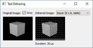
}dither_mode只是在决定使用哪一种抖动。在这里预览双方并排。左边是拜耳抖动式(我画的图案),右边是弗洛伊德-斯坦伯格抖动:

抖动有时会在一些旋转中创建丑陋(平行线)模式,而不变的模式在所有情况下看起来都是平滑的,所以我将坚持我的原始渲染。
Stack Overflow用户
发布于 2021-03-07 16:11:45
…一直是我一直想深入探讨的话题之一。虽然OP总是提供一个自答,但在它出现之前,我已经开始了自己的操作。因此,我想介绍一下我所得到的。
我实现了
- 拜耳抖动
- 弗洛伊德-斯坦伯格抖动
做了一个
- 演示(在Qt中)
- 视觉输出
- 时间比较
这还不够严重,不足以称其为基准,但可能会提供一个提示。
链接的Wikipedia文章提到了一个2×2、4×4和8×8拜耳矩阵的阈值映射,它可以直接在源代码中定义。


相反,我使用了拜耳矩阵的递归定义。

因此,应用相同的函数初始化静态拜耳矩阵进行查找,并在需要时实时计算相关元素。
我的实现:ditherBayer.h
// Bayer Dithering (Ordered Dithering)
// https://en.wikipedia.org/wiki/Ordered_dithering

#ifndef DITHER_BAYER_H
#define DITHER_BAYER_H

// standard C++ header:
#include <cassert>
#include <algorithm>

// own header:
#include "types.h"

// a function for recursive definition of Bayer matrix
template <uint Q>
uint8 mBayer(uint i, uint j);

// specialization for Q == 1
template <>
uint8 mBayer<1>(uint i, uint j)
{
  assert(i < 2); assert(j < 2);
  static uint8 m[2][2] {
    { 0, 2 },
    { 3, 1 }
  };
  return m[i][j];
}

// general case: recursive definition
template <uint Q>
uint8 mBayer(uint i, uint j)
{
  const uint q_1 = Q - 1; // for recursive descent
  const uint mask = ~(1 << q_1);
  return 4 * mBayer<q_1>(i & mask, j & mask)
    + mBayer<1>(i >> q_1, j >> q_1);
}

/* Bayer Dithering
 *
 * Q   : quality 1, 2, 3, 4
 *       The Bayer matrix has dimension 2^Q x 2^Q.
 * MAP : true ... stored matrix for look-up\n
 *       false ... compute matrix values on-the-fly in each call
 *
 * w, h: width and height of images
 * imgMono: buffer for mono image (output)
 *          1 bit per pixel
 * bytesPerRowMono: bytes per row in the mono image
 *          to consider row alignment in case
 * imgGray: buffer for graylevel image (input)
 *          8 bits per pixel
 * bytesPerRowGray: bytes per row in the graylevel image
 *          to consider row alignment in case
 */
template <uint Q, bool MAP>
void ditherBayer(
  uint w, uint h,
  uint8 *imgMono, uint bytesPerRowMono,
  const uint8 *imgGray, uint bytesPerRowGray)
{
  static_assert(Q >= 1); static_assert(Q <= 4);
  const uint n = 1 << Q; // width/height of Bayer matrix (a power of 2)
  const uint mask = n - 1; // a bit mask, used for % n in bit-arith.
  // get pixel (x, y) from gray image
  auto getPixel = [&](uint x, uint y) {
    assert(y < h); assert(x < bytesPerRowGray);
    return imgGray[y * bytesPerRowGray + x];
  };
  // set pixel (x, y) in mono image
  auto setPixel = [&](uint x, uint y, bool value) {
    assert(y < h);
    const uint xByte = x >> 3, xBit = 7 - (x & 7);
    assert(xByte < bytesPerRowMono);
    imgMono[y * bytesPerRowMono + xByte] |= value << xBit;
  };
  // init mono image (clear all bits initially)
  std::fill(imgMono, imgMono + w * h / 8, 0);
  // apply dithering
  if (MAP) { // use look-up matrix
    static uint8 m[n][n];
    if (static bool init = false; !init) {
      for (uint i = 0; i < n; ++i) {
        for (uint j = 0; j < n; ++j) {
          m[i][j] = mBayer<Q>(i, j) << (8 - 2 * Q);
        }
      }
      init = true;
    }
    for (uint y = 0; y < h; ++y) {
      for (uint x = 0; x < w; ++x) {
        setPixel(x, y, getPixel(x, y) > m[y & mask][x & mask]);
      }
    }
  } else { // compute matrix values on-the-fly
    for (uint y = 0; y < h; ++y) {
      for (uint x = 0; x < w; ++x) {
        setPixel(x, y,
          getPixel(x, y) > mBayer<Q>(y & mask, x & mask) << (8 - 2 * Q));
      }
    }
  }
}

#endif // DITHER_BAYER_H因此,我将Bayer矩阵的元素缩放到输入像素范围0,255。因此,输入像素可以直接与当前的拜耳矩阵元素进行比较,从而得到一个0 (黑色)或1 (白色)输出像素值。
链接的维基百科文章强调,抖动可以用于就地抖动(即输入图像被就地修改)。在我的情况下,这是没有意义的,因为我打算保持输入图像不被修改。(在OPs的情况下,像素值是3d渲染的结果,也没有输入图像。)当我从输入映像的副本开始时,我意识到每次只需要连续两行,而算法却在抖动。因此,我将实现更改为只管理对每一行重复使用的两个行缓冲区。
此外,这些行缓冲区可以使用比输入像素类型更大且有符号的像素类型来实现更精确的错误处理。
最后,行缓冲区比行稍大一些,无需处理边框情况(行的第一个和最后一个像素),而无需任何特殊考虑。
我的实现:ditherFloydSteinberg.h
// Floyd-Steinberg Dithering
// https://en.wikipedia.org/wiki/Floyd%E2%80%93Steinberg_dithering

#ifndef DITHER_FLOYD_STEINBERG_H
#define DITHER_FLOYD_STEINBERG_H

// standard C++ header:
#include <cassert>
#include <algorithm>
#include <vector>

/* Floyd-Steinberg Dithering
 *
 * w, h: width and height of images
 * imgMono: buffer for mono image (output)
 *          1 bit per pixel
 * bytesPerRowMono: bytes per row in the mono image
 *          to consider row alignment in case
 * imgGray: buffer for graylevel image (input)
 *          8 bits per pixel
 * bytesPerRowGray: bytes per row in the graylevel image
 *          to consider row alignment in case
 */
void ditherFloydSteinberg(
  uint w, uint h,
  uint8 *imgMono, uint bytesPerRowMono,
  const uint8 *imgGray, uint bytesPerRowGray)
{
  // get pixel (x, y) from gray image
  auto getPixel = [&](uint x, uint y) {
    assert(y < h); assert(x < bytesPerRowGray);
    return imgGray[y * bytesPerRowGray + x];
  };
  // set pixel (x, y) in mono image
  auto setPixel = [&](uint x, uint y, bool value) {
    assert(y < h);
    const uint xByte = x >> 3, xBit = 7 - (x & 7);
    assert(xByte < bytesPerRowMono);
    imgMono[y * bytesPerRowMono + xByte] |= value << xBit;
  };
  // two row buffers
  // for cumulative error compensation
  // and to simplify handling of border cases (hence: w + 2)
  std::vector<int> buffer0(w + 2), buffer1(w + 2);
  int *buffers[2] = { &buffer0[1], &buffer1[1] };
  // copy pixel row y into buffer
  auto initBuffer = [&](int *buffer, uint y)
  {
    buffer[-1] = getPixel(0, y);
    for (uint i = 0; i < w; ++i) buffer[i] = getPixel(i, y);
  };
  // init mono image (clear all bits initially)
  std::fill(imgMono, imgMono + w * h / 8, 0);
  // process pixels
  initBuffer(buffers[0], 0);
  for (uint y = 0; y < h; ++y) {
    if (y + 1 < h) initBuffer(buffers[1], y); // init buffer for next row
    for (int x = 0; x < (int)w; ++x) {
      const int valueOld = buffers[0][x];
      const bool valueNew = valueOld >= 128;
      setPixel(x, y, valueNew);
      const int error = valueOld - valueNew * 0xff;
      buffers[0][x + 1] += error * 7 / 16;
      buffers[1][x - 1] += error * 3 / 16;
      buffers[1][x    ] += error * 5 / 16;
      buffers[1][x + 1] += error * 1 / 16;
    }
    std::swap(buffers[0], buffers[1]); // next row -> current row
  }
}

/* Floyd-Steinberg Dithering in serpentines
 *
 * Every second row is processed from right to left.
 *
 * w, h: width and height of images
 * imgMono: buffer for mono image (output)
 *          1 bit per pixel
 * bytesPerRowMono: bytes per row in the mono image
 *          to consider row alignment in case
 * imgGray: buffer for graylevel image (input)
 *          8 bits per pixel
 * bytesPerRowGray: bytes per row in the graylevel image
 *          to consider row alignment in case
 */
void ditherFloydSteinbergSerp(
  uint w, uint h,
  uint8 *imgMono, uint bytesPerRowMono,
  const uint8 *imgGray, uint bytesPerRowGray)
{
  // get pixel (x, y) from gray image
  auto getPixel = [&](uint x, uint y) {
    assert(y < h); assert(x < bytesPerRowGray);
    return imgGray[y * bytesPerRowGray + x];
  };
  // set pixel (x, y) in mono image
  auto setPixel = [&](uint x, uint y, bool value) {
    assert(y < h);
    const uint xByte = x >> 3, xBit = 7 - (x & 7);
    assert(xByte < bytesPerRowMono);
    imgMono[y * bytesPerRowMono + xByte] |= value << xBit;
  };
  // two row buffers
  // for cumulative error compensation
  // and to simplify handling of border cases (hence: w + 2)
  std::vector<int> buffer0(w + 2), buffer1(w + 2);
  int *buffers[2] = { &buffer0[1], &buffer1[1] };
  // copy pixel row y into buffer
  auto initBuffer = [&](int *buffer, uint y)
  {
    buffer[-1] = getPixel(0, y);
    for (uint i = 0; i < w; ++i) buffer[i] = getPixel(i, y);
  };
  // init mono image (clear all bits initially)
  std::fill(imgMono, imgMono + w * h / 8, 0);
  // process pixels
  initBuffer(buffers[0], 0);
  for (uint y = 0; y < h; ++y) {
    if (y + 1 < h) initBuffer(buffers[1], y); // init buffer for next row
    for (int x = 0; x < (int)w; ++x) {
      const int valueOld = buffers[0][x];
      const bool valueNew = valueOld >= 128;
      setPixel(x, y, valueNew);
      const int error = valueOld - valueNew * 0xff;
      buffers[0][x + 1] += error * 7 / 16;
      buffers[1][x - 1] += error * 3 / 16;
      buffers[1][x    ] += error * 5 / 16;
      buffers[1][x + 1] += error * 1 / 16;
    }
    std::swap(buffers[0], buffers[1]); // next row -> current row
    // next iteration (unrolled)
    if (++y == h) break;
    if (y + 1 < h) initBuffer(buffers[1], y);
    for (int x = w; x--;) {
      const int valueOld = buffers[0][x];
      const bool valueNew = valueOld >= 192;
      setPixel(x, y, valueNew);
      const int error = valueOld - valueNew * 0xff;
      buffers[0][x - 1] += error * 7 / 16;
      buffers[1][x + 1] += error * 3 / 16;
      buffers[1][x    ] += error * 5 / 16;
      buffers[1][x - 1] += error * 1 / 16;
    }
    std::swap(buffers[0], buffers[1]); // next row -> current row
  }
}

#endif // DITHER_FLOYD_STEINBERG_H
演示(在Qt中)
作为一个示例,我编写了一个小的Qt程序。Qt提供了基本的图像处理(包括。PNG和JPEG文件加载器)。因此,几乎没有必要的代码来为此提供一个MCVE。
types.h
#ifndef TYPES_H
#define TYPES_H

#include <cstdint>

// convenience types

using uint = unsigned;
using ulong = unsigned long;
using uint8 = std::uint8_t;
using uint16 = std::uint16_t;

#endif // TYPES_H
testQImageDithering.cc
// Qt header:
#include <QtWidgets>

// own header:
#include "types.h"
#include "ditherBayer.h"
#include "ditherFloydSteinberg.h"

/* ensures that the output image has proper size and format
 *
 * qImgMono output image (mono image)
 * qImgGray input image (graylevel image)
 */
void adjustMonoImage(
  QImage &qImgMono, const QImage &qImgGray)
{
  if (qImgMono.format() != QImage::Format_Mono
    || qImgMono.width() != qImgGray.width()
    || qImgMono.height() != qImgGray.height()) {
    qImgMono
      = QImage(qImgGray.width(), qImgGray.height(), QImage::Format_Mono);
  }
}

// convenience types for std::chrono

using Clock = std::chrono::steady_clock;
using Time = Clock::time_point;
using USecs = std::chrono::microseconds;

/* provides a wrapper function to apply the dither algorithms
 * to QImage objects.
 *
 * return: duration in microseconds
 */
template <void (*FUNC)(uint, uint, uint8*, uint, const uint8*, uint)>
ulong dither(
  QImage &qImgMono, const QImage &qImgGray)
{
  adjustMonoImage(qImgMono, qImgGray);
  const Time t0 = Clock::now();
  FUNC((uint)qImgGray.width(), (uint)qImgGray.height(),
    qImgMono.bits(), qImgMono.bytesPerLine(),
    qImgGray.bits(), qImgGray.bytesPerLine());
  const Time t1 = Clock::now();
  return std::chrono::duration_cast<USecs>(t1 - t0).count();
}

// main application
int main(int argc, char **argv)
{
  qDebug() << "Qt Version:" << QT_VERSION_STR;
  QApplication app(argc, argv);
  // setup data
  QImage qImg("test.jpg");
  QImage qImgG = qImg.convertToFormat(QImage::Format_Grayscale8);
  QImage qImgDith(qImgG.width(), qImgG.height(), QImage::Format_Mono);
  // dithering algorithms
  using DitherFunc = ulong(QImage&, const QImage&);
  using DitherSlot = std::function<DitherFunc>;
  using FuncEntry = std::pair<QString, DitherSlot>;
  FuncEntry tblDither[] = {
    { "Bayer (2 x 2, table)", &dither<ditherBayer<1, true>> },
    { "Bayer (4 x 4, table)", &dither<ditherBayer<2, true>> },
    { "Bayer (8 x 8, table)", &dither<ditherBayer<3, true>> },
    { "Bayer (2 x 2, func.)", &dither<ditherBayer<1, false>> },
    { "Bayer (4 x 4, func.)", &dither<ditherBayer<2, false>> },
    { "Bayer (8 x 8, func.)", &dither<ditherBayer<3, false>> },
    { "Floyd Steinberg", &dither<ditherFloydSteinberg> },
    { "Floyd Steinberg (serp.)", &dither<ditherFloydSteinbergSerp> }
  };
  // setup GUI
  QWidget qWinMain;
  qWinMain.setWindowTitle("Test Dithering");
  //qWinMain.resize(800, 600);
  QGridLayout qGrid;
  QHBoxLayout qHBoxImgOrig;
  QLabel qLblImgOrig("Original Image:");
  qHBoxImgOrig.addWidget(&qLblImgOrig);
  QCheckBox qTglImgOrigGray("Gray");
  qTglImgOrigGray.setChecked(true);
  qHBoxImgOrig.addWidget(&qTglImgOrigGray, 1);
  qGrid.addLayout(&qHBoxImgOrig, 0, 0);
  QHBoxLayout qHBoxImgDith;
  QLabel qLblImgDith("Dithered Image:");
  qHBoxImgDith.addWidget(&qLblImgDith);
  QComboBox qCBoxFuncDith;
  for (const FuncEntry &entry : tblDither) {
    qCBoxFuncDith.addItem(entry.first);
  }
  qHBoxImgDith.addWidget(&qCBoxFuncDith, 1);
  qGrid.addLayout(&qHBoxImgDith, 0, 1);
  QLabel qViewImgOrig;
  qGrid.addWidget(&qViewImgOrig, 1, 0);
  QLabel qViewImgDith;
  qGrid.addWidget(&qViewImgDith, 1, 1);
  QLabel qLblDTDith("Duration:");
  qGrid.addWidget(&qLblDTDith, 2, 1);
  qGrid.setRowStretch(1, 1);
  qWinMain.setLayout(&qGrid);
  qWinMain.show();
  // install signal handlers
  auto updateImgOrig = [&]() {
    qViewImgOrig.setPixmap(
      QPixmap::fromImage(qTglImgOrigGray.isChecked() ? qImgG : qImg));
  };
  auto updateImgDith = [&]() {
    const int i = qCBoxFuncDith.currentIndex();
    const ulong dt = i < 0
      ? qImgDith.fill(0), 0ul
      : tblDither[i].second(qImgDith, qImgG);
    qViewImgDith.setPixmap(QPixmap::fromImage(qImgDith));
    qLblDTDith.setText(QString::fromUtf8("Duration: %1 \xce\xbcs").arg(dt));
  };
  updateImgOrig();
  updateImgDith();
  QObject::connect(&qTglImgOrigGray, &QCheckBox::toggled,
    [&](bool) { updateImgOrig(); });
  QObject::connect(&qCBoxFuncDith, QOverload<int>::of(&QComboBox::currentIndexChanged),
    [&](int) { updateImgDith(); });
  // runtime loop
  return app.exec();
}
为了比较不同算法的视觉效果,我用了我的一只猫的照片。我选择了这个,因为这只猫是黑色的。因此,这张照片由许多灰色阴影组成,我认为这是抖动算法的一项雄心勃勃的任务。
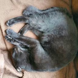
Moritz,猫(256×256像素)-转换为灰度进行测试
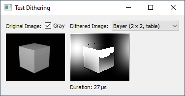
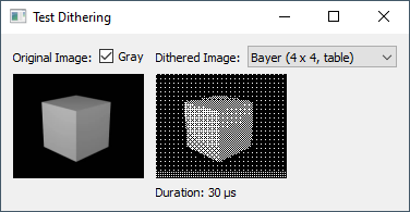
视觉输出
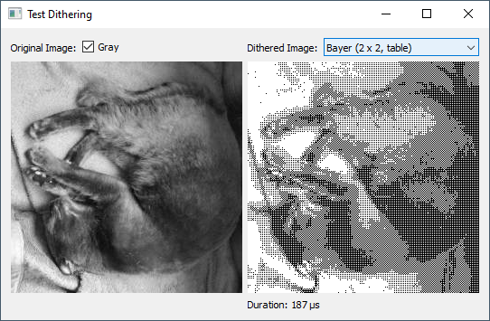
拜耳抖动(2×2)
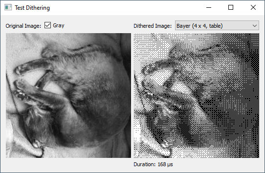
拜耳抖动(4×4)
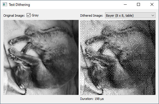
拜耳抖动(8×8)

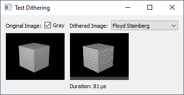
弗洛伊德-斯坦伯格抖动
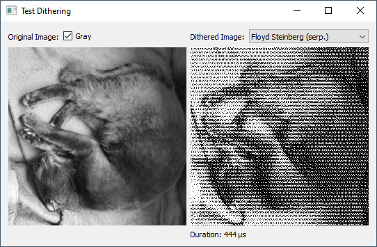
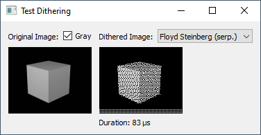
弗洛伊德-斯坦伯格抖动(以蛇为单位)
虽然这可能会给人留下不同的抖动方法的视觉效果的印象,但是时间的安排应该是一丝不苟的。
时间比较
在玩演示时,我注意到计算持续时间的输出中有大量的噪声。因此,我使用另一个图像,1024×576像素,以获得一些时间。下表提供了一个总的印象,没有声称被认为是严肃的基准。
Method                  │ Duration (μs)
────────────────────────┼──────────────
Bayer (2 x 2, table)    │     1371
Bayer (4 x 4, table)    │     1368
Bayer (8 x 8, table)    │     1371
Bayer (2 x 2, func.)    │     1481
Bayer (4 x 4, func.)    │     1862
Bayer (8 x 8, func.)    │     2473
Floyd Steinberg         │     4037
Floyd Steinberg (serp.) │     4396
调查结果:
- 对于使用预先计算表的拜耳抖动,拜耳矩阵的大小影响较小.
- 如果Bayer矩阵元素是动态计算的(使用递归函数),则不是这样。应该在编译时展开递归并不改变这一事实。
- 弗洛伊德-斯坦伯格的抖动在总体上要慢一些(尽管我认为视觉效果更好)。
- 和(serp.)是否定的。(在玩游戏的时候,我也经常看到相反的关系。)

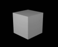
OP的样本图像:
输出:
注:
三思OPs三维渲染…应用拜耳抖动可能非常容易,而对于抖动则不是那么容易(每个像素都会影响右边和底部的邻居)。
https://stackoverflow.com/questions/66503903
复制相似问题
腾讯云开发者
