
如何按预期顺序绘制子控件和自定义绘图?
我控制自定义图纸,让我们称之为Surface。
我想在那个Surface中嵌入一些winforms控件。但我也想画一些自定义的图纸(连接器),取决于控制位置,大小等。
我试着让孩子们自己画这些连接器,所以我的任何一个子控件都是更大的,包括所有必要的图纸。当需要时,我使用Parent.InvokePaint调用来绘制父背景(我也尝试过透明背景)。
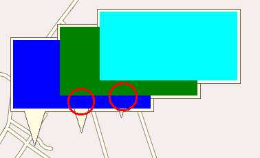
的缺点:当父背景在子OnPaint事件中绘制时,它会擦除已经绘制的所有其他相同的控件。下图显示了结果。彩色区域是子控件的内容。

我还尝试将绘制连接器到Surface并将子控件添加到Surface.Controls列表中的责任赋予。
的缺点:子控件总是绘制在我的自定义绘图之上(这发生在Surface.OnPaint中),因为它们的绘制在队列后面的某个时候会发生。
我的要求是:
我需要在我的Surface内的可行的控制(接收任何鼠标和键盘事件,可聚焦,等等)。每个控件都有一些自定义的连接器来显示表面上的上下文。当控件重叠时,我希望一切都按预期顺序显示。
如何做到这一点?
回答 3
Stack Overflow用户
发布于 2011-07-21 01:36:29
我找到了解决问题的简单办法。
我刚刚使用了子控件的“区域”属性(弹出)来设置裁剪路径:
GraphicsPath path = new GraphicsPath();
// add some shapes to path here, describing the control shape
// ...
this.Region = new Region(path);
我以前不知道定制路径剪裁。
Stack Overflow用户
发布于 2011-07-20 02:24:00
当需要调整WinForm上控件的z顺序时,可以使用控件的SendToFront和SendToBack方法。更好的解决方案是转到控件的容器。容器的Controls属性中有一个SetChildIndex方法,它可以独立地设置包含的控件的z顺序。
Stack Overflow用户
发布于 2018-09-24 16:11:35
@Dimitry -谢谢C#的信息。这个问题确实帮助我开始将自定义图形放到自定义控件上。但是,我使用的是Visual .NET,因此这里有一些更详细的内容和一个VB透视图。将图形放置在表面上的Z顺序也很关键。这是因为无法更改Drawing2D对象(如.GrahicsPath和.FillRectangle)的z顺序;只能更改控件的Zorder。若要隐藏现有控件的一部分,并在其上绘制箭头,步骤如下。整个方法应该放在控件的make事件中;然后需要小心,以确保只要控件被重新绘制,就会触发油漆事件(这是另一个故事!):
- 创建附加到控件的Graphics对象
- 刷新控件
- 填充一个矩形以隐藏控件现有信息的一部分。
- 创建和设置所需的形状为剪裁掩码(在下面的代码示例中,一个箭头)
- 用所需的颜色/图像或任何所需的东西填充形状。
在下面的示例中,应用于基于ListView的自定义控件中,将创建一个箭头并将箭头放置在标头的左侧。它遮住了不需要的CheckBox,将所需的CheckBox保留在视图中,如下所示:
自从你贴出你的问题和先前的答案以来,已经过去了几年。也许现在.NET帮助中的好信息是从那时开始添加的。找到它是这里与更多的细节和链接。
Protected Overrides Sub OnPaint(ByVal e As System.Windows.Forms.PaintEventArgs)       'This is traps the default OnPaint for a Component, so it starts by calling the Base's Paint Event
    MyBase.OnPaint(e)

    'Add your custom paint code here - in this example, a Green Arrow
    AddArrowOverHeaderCheckBox()
End Sub
Private Sub AddArrowOverHeaderCheckBox()
    'Adds an Arrow that is placed over the Checkbox of the 0th row, of a ListView, (over a Row that is used as a Header in this Custom Control).

    'Create a Rectangle into which to put the arrow
    Dim G As Graphics = Me.CreateGraphics               'Attach a Graphics Object to the Base
    Dim lvsi As ListViewItem.ListViewSubItem = Me.Items(0).SubItems(0)   'Get the first row; it is being used as a header in this case
    Dim CheckBoxWidth As Integer = Me.Bounds.X          'Calculate the size of the Control's CheckBox
    Dim CheckBoxHeight As Integer = lvsi.Bounds.Height
    Dim InflateBy As Integer = 1                        'Optional amount to resize the area in which the Arrow is to be placed
    Me.Refresh()                                        'Refresh the ListViewTab so that it does not overpaint the arrow that is about to be created at the End Sub
    Dim I As Integer = 0
    I = (CheckBoxHeight + 1) Mod 2
    Dim R As Rectangle = New Rectangle(lvsi.Bounds.X + Me.Margin.Left, lvsi.Bounds.Top, CheckBoxWidth, CheckBoxHeight + I) 'Make sure the height is an Odd number, to make a tidy arrow
    'myBrush.Color = Color.Red
    R.Inflate(InflateBy * 2, InflateBy)                  'Create a covering rectangle that is larger than the CheckBox on the Left of the CheckView Item in both dimensions
    Dim myBrush As New System.Drawing.SolidBrush(Me.BackColor)
    G.FillRectangle(myBrush, R)                         'Draw a filled Rectangle over the CheckBox in the Background colour for the ListViewTab to obscure the CheckBox
    Dim RW = R.Width
    Dim RH = R.Height
    I = CSng(RH) * 0.5 \ 2                              'Set a proportion of the arrow's width for its shaft, here 50%
    If RH Mod 2 <> 0 Then RH += 1                       'Ensure that the Height is an Odd number to make the Arrow axially symmetric
    '                                                   'Create a polygon in an Arrow shape that fits inside the Rectangle
    Dim polyArrow As Point() = {New Point(R.X + 0, I + R.Y), New Point(R.X + RW * 0.4, I + R.Y), New Point(R.X + RW * 0.4, 0 + R.Y), New Point(R.X + RW, RH * 0.5 + R.Y),
                                New Point(R.X + RW * 0.4, RH + R.Y), New Point(R.X + RW * 0.4, RH - I + R.Y), New Point(R.X + 0, RH - I + R.Y)}
    Dim path As New Drawing2D.GraphicsPath()            'Create a Path shaped like an Arrow & sized proportionately to the size of the required Rectangle
    path.AddPolygon(polyArrow)                          'Turn the Path into a polygon
    Dim [reg] As New [Region](path)                     'Define a Graphics Region of the shape of the Arrow
    G.SetClip([reg], combineMode:=Drawing2D.CombineMode.Replace) 'Redefine the area; clipping will now prevent any drawing outside the area of the Arrow
    myBrush.Color = Color.Green
    G.FillRectangle(myBrush, R)                         'Draw a filled Green Rectangle, clipped to the Path shape
    'Dim pen As Pen = Pens.Black                         'Optionally: Draw a fine boundary in black
    'G.DrawPath(pen, path)                               'Optionally: Draw a fine boundary in black
    G.SetClip(Me.ClientRectangle)                       'Remove the Clip from the Graphics area - in case G is re-used
    myBrush.Dispose()                                   'Tidy up
    G.Dispose()
End Subhttps://stackoverflow.com/questions/6756289
复制相似问题
腾讯云开发者
