
未标定立体系统的OpenCV深度图
我试着用一种未加标记的方法得到深度图。我可以通过SIFT找到对应点,然后使用cv2.findFundamentalMat获得基本矩阵。然后,我使用cv2.stereoRectifyUncalibrated获得每幅图像的同形矩阵。最后,我使用cv2.warpPerspective来校正和计算视差,但这并不能创建一个很好的深度图。这些值非常高,所以我想知道我是否必须使用warpPerspective,或者我必须从stereoRectifyUncalibrated得到的同形矩阵中计算出一个旋转矩阵。
我不确定射影矩阵是用stereoRectifyUncalibrated得到的同形矩阵来校正的。
守则的一部分:
#Obtainment of the correspondent point with SIFT
sift = cv2.SIFT()

###find the keypoints and descriptors with SIFT
kp1, des1 = sift.detectAndCompute(dst1,None)
kp2, des2 = sift.detectAndCompute(dst2,None)

###FLANN parameters
FLANN_INDEX_KDTREE = 0
index_params = dict(algorithm = FLANN_INDEX_KDTREE, trees = 5)
search_params = dict(checks=50)

flann = cv2.FlannBasedMatcher(index_params,search_params)
matches = flann.knnMatch(des1,des2,k=2)

good = []
pts1 = []
pts2 = []

###ratio test as per Lowe's paper
for i,(m,n) in enumerate(matches):
    if m.distance < 0.8*n.distance:
        good.append(m)
        pts2.append(kp2[m.trainIdx].pt)
        pts1.append(kp1[m.queryIdx].pt)


pts1 = np.array(pts1)
pts2 = np.array(pts2)

#Computation of the fundamental matrix
F,mask= cv2.findFundamentalMat(pts1,pts2,cv2.FM_LMEDS)


# Obtainment of the rectification matrix and use of the warpPerspective to transform them...
pts1 = pts1[:,:][mask.ravel()==1]
pts2 = pts2[:,:][mask.ravel()==1]

pts1 = np.int32(pts1)
pts2 = np.int32(pts2)

p1fNew = pts1.reshape((pts1.shape[0] * 2, 1))
p2fNew = pts2.reshape((pts2.shape[0] * 2, 1))

retBool ,rectmat1, rectmat2 = cv2.stereoRectifyUncalibrated(p1fNew,p2fNew,F,(2048,2048))

dst11 = cv2.warpPerspective(dst1,rectmat1,(2048,2048))
dst22 = cv2.warpPerspective(dst2,rectmat2,(2048,2048))

#calculation of the disparity
stereo = cv2.StereoBM(cv2.STEREO_BM_BASIC_PRESET,ndisparities=16*10, SADWindowSize=9)
disp = stereo.compute(dst22.astype(uint8), dst11.astype(uint8)).astype(np.float32)
plt.imshow(disp);plt.colorbar();plt.clim(0,400)#;plt.show()
plt.savefig("0gauche.png")

#plot depth by using disparity focal length `C1[0,0]` from stereo calibration and `T[0]` the distance between cameras
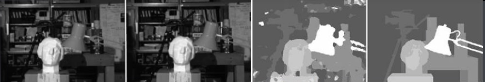
plt.imshow(C1[0,0]*T[0]/(disp),cmap='hot');plt.clim(-0,500);plt.colorbar();plt.show()下面是使用未绑定方法(和warpPerspective)进行校正的图片:
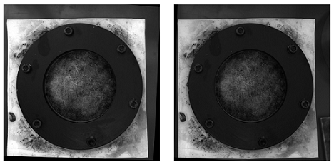
以下是用校准方法校正的图片:
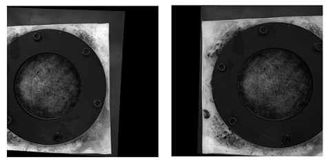
我不知道这两种照片之间的区别为何如此重要。而对于校准的方法,它似乎不对齐。
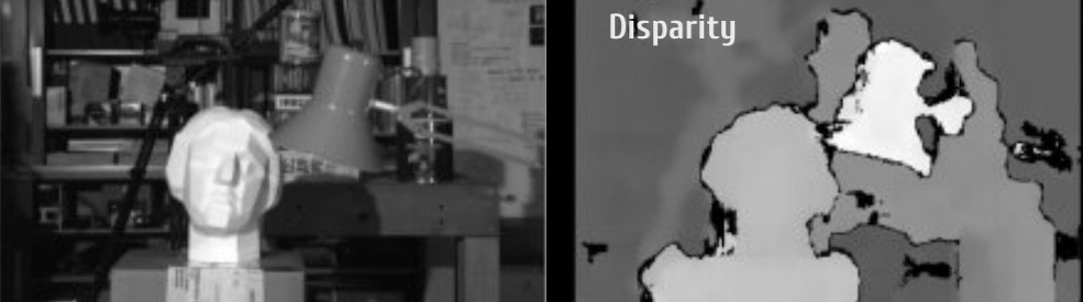
使用未加标记方法绘制的视差图:
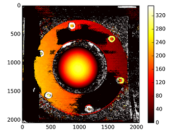
深度用:C1[0,0]*T[0]/(disp)和来自stereoCalibrate的T来计算。价值很高。
-稍后编辑
我尝试用“(Devernay97,”得到的同调矩阵“装入”重建矩阵(Devernay97,Garcia01),但结果仍然不太好。我做得对吗?
Y=np.arange(0,2048)
X=np.arange(0,2048)
(XX_field,YY_field)=np.meshgrid(X,Y)

#I mount the X, Y and disparity in a same 3D array
stock = np.concatenate((np.expand_dims(XX_field,2),np.expand_dims(YY_field,2)),axis=2)
XY_disp = np.concatenate((stock,np.expand_dims(disp,2)),axis=2)

XY_disp_reshape = XY_disp.reshape(XY_disp.shape[0]*XY_disp.shape[1],3)

Ts = np.hstack((np.zeros((3,3)),T_0)) #i use only the translations obtained with the rectified calibration...Is it correct?


# I establish the projective matrix with the homography matrix
P11 = np.dot(rectmat1,C1)
P1 = np.vstack((np.hstack((P11,np.zeros((3,1)))),np.zeros((1,4))))
P1[3,3] = 1

# P1 = np.dot(C1,np.hstack((np.identity(3),np.zeros((3,1)))))

P22 = np.dot(np.dot(rectmat2,C2),Ts)
P2 = np.vstack((P22,np.zeros((1,4))))
P2[3,3] = 1

lambda_t = cv2.norm(P1[0,:].T)/cv2.norm(P2[0,:].T)


#I define the reconstruction matrix
Q = np.zeros((4,4))

Q[0,:] = P1[0,:].T
Q[1,:] = P1[1,:].T
Q[2,:] = lambda_t*P2[1,:].T - P1[1,:].T
Q[3,:] = P1[2,:].T

#I do the calculation to get my 3D coordinates
test = []
for i in range(0,XY_disp_reshape.shape[0]):
    a = np.dot(inv(Q),np.expand_dims(np.concatenate((XY_disp_reshape[i,:],np.ones((1))),axis=0),axis=1))
    test.append(a)

test = np.asarray(test)

XYZ = test[:,:,0].reshape(XY_disp.shape[0],XY_disp.shape[1],4)Stack Overflow用户
发布于 2020-06-27 04:39:43
可能有几个可能的问题,导致低质量的Depth Channel和Disparity Channel导致我们的低质量立体声序列。以下是其中6个问题:
可能的问题一
- 不完全公式
正如单词uncalibrated所暗示的,stereoRectifyUncalibrated实例方法为您计算一个校正转换,以防您不知道或无法知道立体声对的内在参数及其在环境中的相对位置。
cv.StereoRectifyUncalibrated(pts1, pts2, fm, imgSize, rhm1, rhm2, thres)其中:
# pts1    –> an array of feature points in a first camera
# pts2    –> an array of feature points in a first camera
# fm      –> input fundamental matrix
# imgSize -> size of an image
# rhm1    -> output rectification homography matrix for a first image
# rhm2    -> output rectification homography matrix for a second image
# thres   –> optional threshold used to filter out outliers
你的方法看起来是这样的:
cv2.StereoRectifyUncalibrated(p1fNew, p2fNew, F, (2048, 2048))因此,您没有考虑三个参数:rhm1、rhm2和thres。如果是threshold > 0,所有不符合极几何的点对在计算同态之前都会被拒绝。否则,所有的点都被认为是不稳定的。这个公式如下所示:
(pts2[i]^t * fm * pts1[i]) > thres

# t   –> translation vector between coordinate systems of cameras
因此,我认为,由于公式计算不完整,可能会出现视觉上的不准确。
您可以在官方资源上阅读摄像机标定与三维重建。
可能的问题二
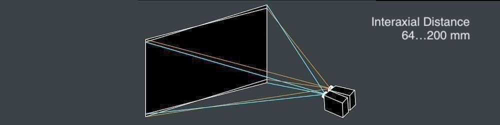
- 轴间距离
左右相机镜头之间的健壮的not greater than 200 mm.必须是interaxial distance。当interaxial distance大于interocular距离时,这种效应称为hyperstereoscopy或hyperdivergence,不仅在场景中造成了深度夸张,而且给观众带来了身体上的不便。阅读Autodesk的立体摄制白纸,了解有关此主题的更多信息。
可能的问题三
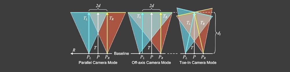
- 并行对位相机模式
由于不正确的相机模式计算,结果Disparity Map中的视觉不准确可能会发生。许多立体技师更喜欢Toe-In camera mode,但皮克斯更喜欢Parallel camera mode。

可能的问题四
- 垂直对准
在立体镜中,如果发生垂直移位(即使其中一个视图被向上移动1毫米),它会破坏一个健壮的立体声体验。因此,在生成Disparity Map之前,您必须确保立体声对的左视图和右视图相应地对齐。看看彩色立体白纸,关于15个常见的立体声问题。
立体校正矩阵:
   ┌                  ┐
   |  f   0   cx  tx  |
   |  0   f   cy  ty  |   # use "ty" value to fix vertical shift in one image
   |  0   0   1   0   |
└ ┘下面是一个StereoRectify方法:
cv.StereoRectify(cameraMatrix1, cameraMatrix2, distCoeffs1, distCoeffs2, imageSize, R, T, R1, R2, P1, P2, Q=None, flags=CV_CALIB_ZERO_DISPARITY, alpha=-1, newImageSize=(0, 0)) -> (roi1, roi2)可能的问题五
- 透镜畸变
镜头畸变是立体声合成中非常重要的课题。在生成一个Disparity Map之前,您需要对左视图和右视图进行反扭曲,然后生成一个视差通道,然后再重新扭曲两个视图。

可能的问题六
- 低质量无混叠深度信道
要创建一个高质量的Disparity Map,您需要左、右Depth Channels,它必须是预先生成的。当你工作在3D包,你可以渲染一个高质量的深度通道(与脆边),只需一次点击。但是,从视频序列生成高质量的深度通道并不容易,因为立体声对必须在您的环境中移动,以便为未来的深度移动算法生成初始数据。如果帧中没有运动,深度通道就会非常差。
另外,
Depth通道本身还有一个缺点--它的边缘不匹配RGB的边缘,因为没有反混叠。

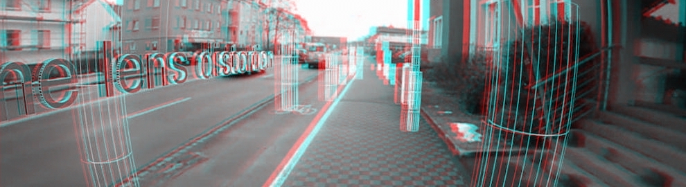
视差信道代码片段:
在这里,我想表示一种快速生成Disparity Map的方法
import numpy as np
import cv2 as cv
from matplotlib import pyplot as plt

imageLeft = cv.imread('paris_left.png', 0)
imageRight = cv.imread('paris_right.png', 0)
stereo = cv.StereoBM_create(numDisparities=16, blockSize=15)
disparity = stereo.compute(imageLeft, imageRight)
plt.imshow(disparity, 'gray')
plt.show()
https://stackoverflow.com/questions/36172913
复制相似问题
腾讯云开发者
