
VTK不能用vtkClipClosedSurface构造适当的闭曲面
以下是我在vtk中所做工作的粗略解释
- 创建一个曲面(一个极小的曲面,不太相关它是什么,几何是很重要的:陀螺仪有两个迷宫,完全关闭彼此)。
- 使用
vtkClipClosedSurface关闭一个迷宫,这样我就可以得到一个没有打开表面的物体。一个规则表面如下所示,有一个封闭的表面,它看起来像像这样。
我的问题是:对于更复杂的结构版本,我理解如下:
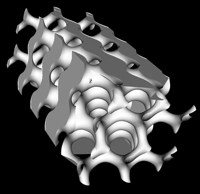
你能看到左上角是如何工作的吗?在右下角附近,它停止了曲面的创建?有时我也会在最后那部分得到很奇怪的三角形。
据我所知,vtkClipClosedSurface从表面法线知道在哪里关闭一个表面,哪里不关闭。问题是:我的结构的法线很好,它们都指向正确的方向。如果你仔细观察一下结构,你会发现下半部分基本上是顶部的反转,它会逐渐变化,都在一个表面上。
在使用vtkSmoothPolyDataFilter、vtkCleanPolyData或vtkPolyDataNormals等许多东西之前,我尝试修改自己的结构。我甚至尝试用vtkFeatureEdges提取边界曲面,结果更加糟糕。即使是vtkFillHolesFilter也没有产生任何可接受的结果。我的表面看起来完美无瑕,很容易创造一个边界。
我不知道还能尝试什么。其他结构也会出现这种情况。用CAD工具修复它是没有问题的,因为它应该是开箱即用的。请帮帮我!
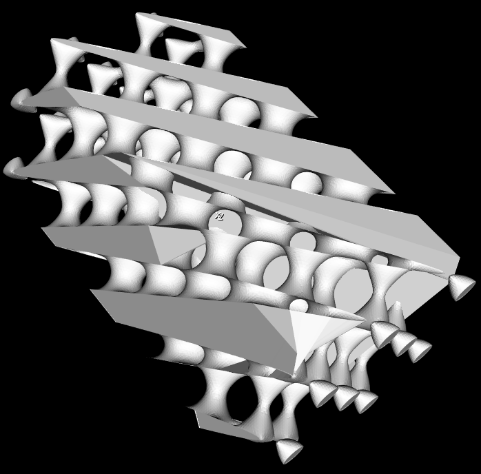
这是另一个几何学的例子,它不能正确地关闭曲面。这一次我使用了vtkFillHolesFilter,它导致结构内部的表面,而它们应该只占据te对象的边界。
如果您需要更详细地分析我的管道,请看下面的内容:
- 使用
mayavi.mlab.contour3d创建曲面 - 通过提取
PolyData来获取actor.mapper.input - 将格式从
tvtk转换为常规vtk vtkClipClosedSurface具有一个平面集合,该集合可以割断部分结构(当平面集合与结构边界相同时会发生错误)。- 形象化
编辑:好的,这没有得到足够的关注,所以我构建了一个最小、完整和可验证的工作示例来复制这种行为:
import numpy as np
import vtk  # VTK version 7.0
from mayavi import mlab  # mayavi version 4.4.4
from mayavi.api import Engine, OffScreenEngine
from tvtk.api import tvtk


def schwarz_D(x, y, z, linear_term=0):
        """This is the function for the Schwarz Diamond level surface."""
        return (np.sin(x) * np.sin(y) * np.sin(z) + np.sin(x) * np.cos(y) * np.cos(z) +
                np.cos(x) * np.sin(y) * np.cos(z) + np.cos(x) * np.cos(y) * np.sin(z)) - linear_term * z


def plane_collection(xn, x, yn, y, zn, z):
        """Defines the 6 planes for cutting rectangular objects to the right size."""
        plane1 = vtk.vtkPlane()
        plane1.SetOrigin(x, 0, 0)
        plane1.SetNormal(-1, 0, 0)
        plane2 = vtk.vtkPlane()
        plane2.SetOrigin(0, y, 0)
        plane2.SetNormal(0, -1, 0)
        plane3 = vtk.vtkPlane()
        plane3.SetOrigin(0, 0, z)
        plane3.SetNormal(0, 0, -1)
        plane4 = vtk.vtkPlane()
        plane4.SetOrigin(xn, 0, 0)
        plane4.SetNormal(1, 0, 0)
        plane5 = vtk.vtkPlane()
        plane5.SetOrigin(0, yn, 0)
        plane5.SetNormal(0, 1, 0)
        plane6 = vtk.vtkPlane()
        plane6.SetOrigin(0, 0, zn)
        plane6.SetNormal(0, 0, 1)

        plane_list = [plane4, plane1, plane5, plane2, plane6, plane3]
        planes = vtk.vtkPlaneCollection()
        for item in plane_list:
            planes.AddItem(item)
        return planes

[nx, ny, nz] = [2, 2, 8]  # amount of unit cells
cell_size = 1
gradient_value = 0.04  # only values below 0.1 produce the desired geometry; this term is essential
x, y, z = np.mgrid[-cell_size*(nx + 1)/2:cell_size*(nx + 1)/2:100j,
                   -cell_size*(ny + 1)/2:cell_size*(ny + 1)/2:100j,
                   -cell_size*(nz + 1)/2:cell_size*(nz + 1)/2:100*2j] * np.pi / (cell_size/2)

# engine = Engine()
engine = OffScreenEngine()  # do not start mayavi GUI
engine.start()
fig = mlab.figure(figure=None, engine=engine)
contour3d = mlab.contour3d(x, y, z, schwarz_D(x, y, z, gradient_value), figure=fig)

scene = engine.scenes[0]
actor = contour3d.actor.actors[0]
iso_surface = scene.children[0].children[0].children[0]
iso_surface.contour.minimum_contour = 0
iso_surface.contour.number_of_contours = 1
iso_surface.compute_normals = False

iso_surface.contour.auto_update_range = False

mlab.draw(fig)
# mlab.show()  # enable if you want to see the mayavi GUI

polydata = tvtk.to_vtk(actor.mapper.input)  # convert tvtkPolyData to vtkPolyData

# Move object to the coordinate center to make clipping easier later on.
center_coords = np.array(polydata.GetCenter())
center = vtk.vtkTransform()
center.Translate(-center_coords[0], -center_coords[1], -center_coords[2])
centerFilter = vtk.vtkTransformPolyDataFilter()
centerFilter.SetTransform(center)
centerFilter.SetInputData(polydata)
centerFilter.Update()

# Reverse normals in order to receive a closed surface after clipping
reverse = vtk.vtkReverseSense()
reverse.SetInputConnection(centerFilter.GetOutputPort())
reverse.ReverseNormalsOn()
reverse.ReverseCellsOn()
reverse.Update()

bounds = np.asarray(reverse.GetOutput().GetBounds())
clip = vtk.vtkClipClosedSurface()
clip.SetInputConnection(reverse.GetOutputPort())
clip.SetTolerance(10e-3)
# clip.TriangulationErrorDisplayOn()  # enable to see errors for not watertight surfaces
clip.SetClippingPlanes(plane_collection(bounds[0] + cell_size/2, bounds[1] - cell_size/2,
                                        bounds[2] + cell_size/2, bounds[3] - cell_size/2,
                                        bounds[4] + cell_size/2, bounds[5] - cell_size/2))
clip.Update()

# Render the result
mapper = vtk.vtkPolyDataMapper()
mapper.SetInputConnection(clip.GetOutputPort())
actor = vtk.vtkActor()
actor.SetMapper(mapper)
renderer = vtk.vtkRenderer()
renderWindow = vtk.vtkRenderWindow()
renderWindow.AddRenderer(renderer)
renderWindowInteractor = vtk.vtkRenderWindowInteractor()
renderWindowInteractor.SetRenderWindow(renderWindow)
renderer.AddActor(actor)
renderWindow.Render()
renderWindowInteractor.Start()
这真的很短,我尽可能地脱光了衣服。问题仍然存在,我想不出解决办法。
回答 2
Stack Overflow用户
发布于 2020-07-11 12:55:17
尝试使用肉汤。我有一个非常类似的问题,一些低分辨率的曼德尔鳞茎,我正在生产。
您可能还想查看pyvista,它是vtk的一个不错的python包装器。
Stack Overflow用户
发布于 2020-09-08 05:15:02
很大的问题,谢谢你的例子。
在pyvista中,经过一些修改,我能够让它工作起来:
import numpy as np
import pyvista as pv


def schwarz_D(x, y, z, linear_term=0):
        """This is the function for the Schwarz Diamond level surface."""
        return (np.sin(x) * np.sin(y) * np.sin(z) + np.sin(x) * np.cos(y) * np.cos(z) +
                np.cos(x) * np.sin(y) * np.cos(z) + np.cos(x) * np.cos(y) * np.sin(z)) - linear_term * z


# Create the grid
[nx, ny, nz] = [2, 2, 8]  # amount of unit cells
cell_size = 1
gradient_value = 0.04  # only values below 0.1 produce the desired geometry; this term is essential
x, y, z = np.mgrid[-cell_size*(nx + 1)/2:cell_size*(nx + 1)/2:100j,
                   -cell_size*(ny + 1)/2:cell_size*(ny + 1)/2:100j,
                   -cell_size*(nz + 1)/2:cell_size*(nz + 1)/2:100*2j] * np.pi / (cell_size/2)


# make a grid and exclude cells below 0.1
grid = pv.StructuredGrid(x, y, z)
grid['scalars'] = schwarz_D(x, y, z, gradient_value).ravel(order='F')
contour = grid.clip_scalar(value=0.1)


# make a bunch of clips
# bounds = contour.bounds
# contour.clip(origin=(bounds[0] + cell_size/2, 0, 0), normal='-x', inplace=True)
# contour.clip(origin=(0, bounds[1] - cell_size/2, 0), normal='-y', inplace=True)
# contour.clip(origin=(0, 0, bounds[2] + cell_size/2), normal='-z', inplace=True)
# contour.clip(origin=(bounds[3] - cell_size/2, 0, 0), normal='x', inplace=True)
# contour.clip(origin=(0, bounds[4] + cell_size/2, 0), normal='y', inplace=True)
# contour.clip(origin=(0, 0, bounds[5] - cell_size/2), normal='z', inplace=True)

contour.plot(smooth_shading=True, color='w')
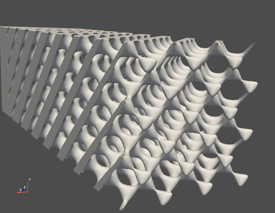
我不知道你为什么要用剪贴板,我想你最好把x,y,z的范围限制在创建网格上。那样的话,你就不用去剪最后的网眼了。
https://stackoverflow.com/questions/37833562
复制相似问题
腾讯云开发者
