
使用cluster_时的子图位置问题
使用cluster_时的子图位置问题
提问于 2016-10-25 20:29:56
我刚刚发现了GraphViz,并试图根据文档和示例创建一个相当简单的网络图。
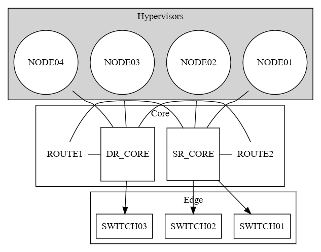
因此,我尝试将其划分为三个主要类别,并希望从上到下排列这三个类别:虚拟机监控程序->核心->边缘。
下面的代码呈现得很好,但是如果我尝试将subgraph core转换为subgraph cluster_core,它就会变得很糟糕。突然,core移动到左边,节点垂直排列(尝试用rankdir和rank=same重写节点)--但我真的想要外部边框和标签!我是不是漏掉了什么?椅子和电脑之间有问题吗?
到目前为止,我的代码是:
digraph network {
  graph [overlap = false]

  // Node definitions
  subgraph core {
    rank = same
    labelloc = c
    label = "Core"

    node [shape=square]
      SR_CORE DR_CORE

    node [shape=plaintext]
      ROUTE2 ROUTE1

  }

  subgraph cluster_hypervisors {
    rank = same
    labelloc = c
    style = filled
    label = "Hypervisors"

    node [shape=circle style=filled fillcolor=white]
      NODE01 NODE02 NODE03 NODE04
  }

  subgraph cluster_edge {
    rank = same
    labelloc = c
    label = "Edge"

    node [shape=rectangle]
      SWITCH01 SWITCH02 SWITCH03
  }

  // Edge definitions
  SR_CORE -> ROUTE2 -> DR_CORE [dir=none]
  SR_CORE -> ROUTE1 -> DR_CORE [dir=none]

  SR_CORE -> { SWITCH01 SWITCH02 }
  DR_CORE -> { SWITCH03 }

  NODE01 -> SR_CORE [dir=back]
  NODE02 -> SR_CORE [dir=back]
  NODE03 -> DR_CORE [dir=back]
  NODE04 -> DR_CORE [dir=back]

}回答 1
Stack Overflow用户
回答已采纳
发布于 2016-11-04 12:24:02
必须使用cluster_core中的{}对节点进行分组。要调整外观,还可以向少数边缘添加一些constraint=false:
digraph network {
  graph [overlap = false]

  // Node definitions
  subgraph cluster_core {
    rank = same
    labelloc = c
    label = "Core"

    node [shape=square]
      SR_CORE DR_CORE

    node [shape=plaintext]
      ROUTE2 ROUTE1

    {SR_CORE DR_CORE ROUTE2 ROUTE1}
  }

  subgraph cluster_hypervisors {
    rank = same
    labelloc = c
    style = filled
    label = "Hypervisors"

    node [shape=circle style=filled fillcolor=white]
      NODE01 NODE02 NODE03 NODE04
  }

  subgraph cluster_edge {
    rank = same
    labelloc = c
    label = "Edge"

    node [shape=rectangle]
      SWITCH01 SWITCH02 SWITCH03
  }

  // Edge definitions
  SR_CORE -> ROUTE2 [dir=none]
  SR_CORE -> ROUTE1 [dir=none, constraint=false]
  ROUTE2 -> DR_CORE [dir=none, constraint=false]
  ROUTE1 -> DR_CORE [dir=none, constraint=false]

  SR_CORE -> { SWITCH01 SWITCH02 }
  DR_CORE -> { SWITCH03 }

  NODE01 -> SR_CORE [dir=back]
  NODE02 -> SR_CORE [dir=back]
  NODE03 -> DR_CORE [dir=back]
  NODE04 -> DR_CORE [dir=back]
}
您可以检查http://graphviz.it/#/mRSLblIF上的工作示例
页面原文内容由Stack Overflow提供。腾讯云小微IT领域专用引擎提供翻译支持
原文链接:
https://stackoverflow.com/questions/40249160
复制相关文章
相似问题
腾讯云开发者
