
用opencv远心单色相机拍摄金属零件孔直径图
设置:
- 照相机:黑蝇S Mono 20.0MP
- 镜头:光学远心透镜TC23080
- 灯:16个绿色LEDS
- Python: 3.7.3
- openCV: 4.0+
抱歉的图像链接,但是有一个图片是20 is左右,也不想松任何质量。
图像样本:
https://drive.google.com/file/d/11PU-5fzvSJt1lKlmP-lQXhdsuCJPGKbN/view?usp=sharing https://drive.google.com/file/d/1B3lSFx8YvTYv3hzuuuYtphoHBuyEdc4o/view
外壳:将有不同形状的金属零件,从5x5到10x10大小(厘米)。在这些金属零件内部,有大量的圆孔在2到10之间,必须非常精确地检测它们。孔的实际大小是未知的,因为有各种各样的可能的部分。我们的目标是用OpenCV编写一个通用算法,它可以与任何金属零件一起工作,并检测圆孔。
我们尝试过的是:我们尝试用HoughCircles算法来检测漏洞,但几乎没有成功。该算法要么太敏感,要么根本不检测漏洞。我们试验了不同的param1和param2值,但没有成功。在使用HoughCircles之前,我们也尝试过模糊图像并将其传递给Canny,但是这种方法并没有产生更好的效果。同样的算法在分辨率较低的图像中效果更好。然而,不能牺牲分辨率,因为准确性在这个项目中是极其重要的。
https://drive.google.com/file/d/1TRdDbperi37bha0uJVALS4C2dBuaNz6u/view?usp=sharing
用下列参数检测到上述圆圈:
minradius=0
maxradius=0
dp=1
param1=100
param2=21
通过使用上述参数,我们几乎可以得到我们想要的结果。当我们对不同的图片使用相同的参数时,问题就出现了。
我们想要得到的最终结果是给定圆的直径,并且精度很高,我们希望相同的算法可以在不同的部分图片上使用。
与其他问题不同的是,我们不知道给定圆的近似半径(因此我们不能操作最小半径、最大半径、param1、param2或任何其他值)。
回答 3
Stack Overflow用户
发布于 2019-07-31 23:31:38
我们知道关于这些图像的两件事:
- 物体是黑色的,背景很亮。
- 这些洞都是圆的,我们要测量所有的洞。
所以我们所要做的就是发现漏洞。实际上,这是非常微不足道的:
- 阈值(背景成为目标,因为它是明亮的)
- 删除边缘对象
剩下的是洞。任何与图像边缘接触的洞都不包括在内。我们现在可以很容易地测量这些洞。既然我们假设它们是圆形的,我们可以做三件事:
- 计算物体像素,这是对区域的无偏估计。从这个区域我们确定了孔的直径。
- 检测轮廓,找到质心,然后使用轮廓点到质心的平均距离作为半径。
- 将图像强度归一化,使背景光强为1,有空穴的物体强度为0。每个孔强度上的积分是对面积的亚像素精度估计(请参阅底部,以获得该方法的快速解释)。
这个使用DIPlib (免责声明:我是作者)的Python代码展示了如何做这三种方法:
import diplib as dip
import numpy as np

img = dip.ImageRead('geriausias.bmp')
img.SetPixelSize(1,'um') # Usually this info is in the image file
bin, thresh = dip.Threshold(img)
bin = dip.EdgeObjectsRemove(bin)
bin = dip.Label(bin)
msr = dip.MeasurementTool.Measure(bin, features=['Size','Radius'])
print(msr)
d1 = np.sqrt(np.array(msr['Size'])[:,0] * 4 / np.pi)
print("method 1:", d1)
d2 = np.array(msr['Radius'])[:,1] * 2
print("method 2:", d2)

bin = dip.Dilation(bin, 10) # we need larger regions to average over so we take all of the light
                            # coming through the hole into account.
img = (dip.ErfClip(img, thresh, thresh/4, "range") - (thresh*7/8)) / (thresh/4)
msr = dip.MeasurementTool.Measure(bin, img, features=['Mass'])
d3 = np.sqrt(np.array(msr['Mass'])[:,0] * 4 / np.pi)
print("method 3:", d3)
这给出了输出:
  |       Size |                                            Radius |
- | ---------- | ------------------------------------------------- |
  |            |        Max |       Mean |        Min |     StdDev |
  |      (µm²) |       (µm) |       (µm) |       (µm) |       (µm) |
- | ---------- | ---------- | ---------- | ---------- | ---------- |
1 |  6.282e+04 |      143.9 |      141.4 |      134.4 |      1.628 |
2 |  9.110e+04 |      171.5 |      170.3 |      168.3 |     0.5643 |
3 |  6.303e+04 |      143.5 |      141.6 |      133.9 |      1.212 |
4 |  9.103e+04 |      171.6 |      170.2 |      167.3 |     0.6292 |
5 |  6.306e+04 |      143.9 |      141.6 |      126.5 |      2.320 |
6 |  2.495e+05 |      283.5 |      281.8 |      274.4 |     0.9805 |
7 |  1.176e+05 |      194.4 |      193.5 |      187.1 |     0.6303 |
8 |  1.595e+05 |      226.7 |      225.3 |      219.8 |     0.8629 |
9 |  9.063e+04 |      171.0 |      169.8 |      167.6 |     0.5457 |

method 1: [282.8250363  340.57242408 283.28834869 340.45277017 283.36249824
 563.64770132 386.9715443  450.65294139 339.70023023]
method 2: [282.74577033 340.58808144 283.24878097 340.43862835 283.1641869
 563.59706479 386.95245928 450.65392268 339.68617582]
method 3: [282.74836803 340.56787463 283.24627163 340.39568372 283.31396961
563.601641 386.89884807 450.62167913 339.68954136]图像bin,在调用dip.Label后,是一个整数图像,其中空穴1的像素都有值1,孔2的像素都有值2,所以我们仍然保持测量大小和孔的大小之间的关系。我没有费心地制作一个标记映像,显示图像上的大小,但这可以很容易地完成,就像您在其他答案中看到的那样。
因为图像文件中没有像素大小信息,所以我给每个像素加了1微米。这可能是不正确的,您将不得不做一个校准,以获得像素大小的信息。
这里的一个问题是背景光照太亮,给出了饱和像素。这会使洞看起来比实际的要大。重要的是校准系统的,使的背景照明接近摄像机可以记录的最大值,而不是在那个最大值或以上。例如,试着使背景强度达到245或250。第三种方法受光照不良的影响最大。
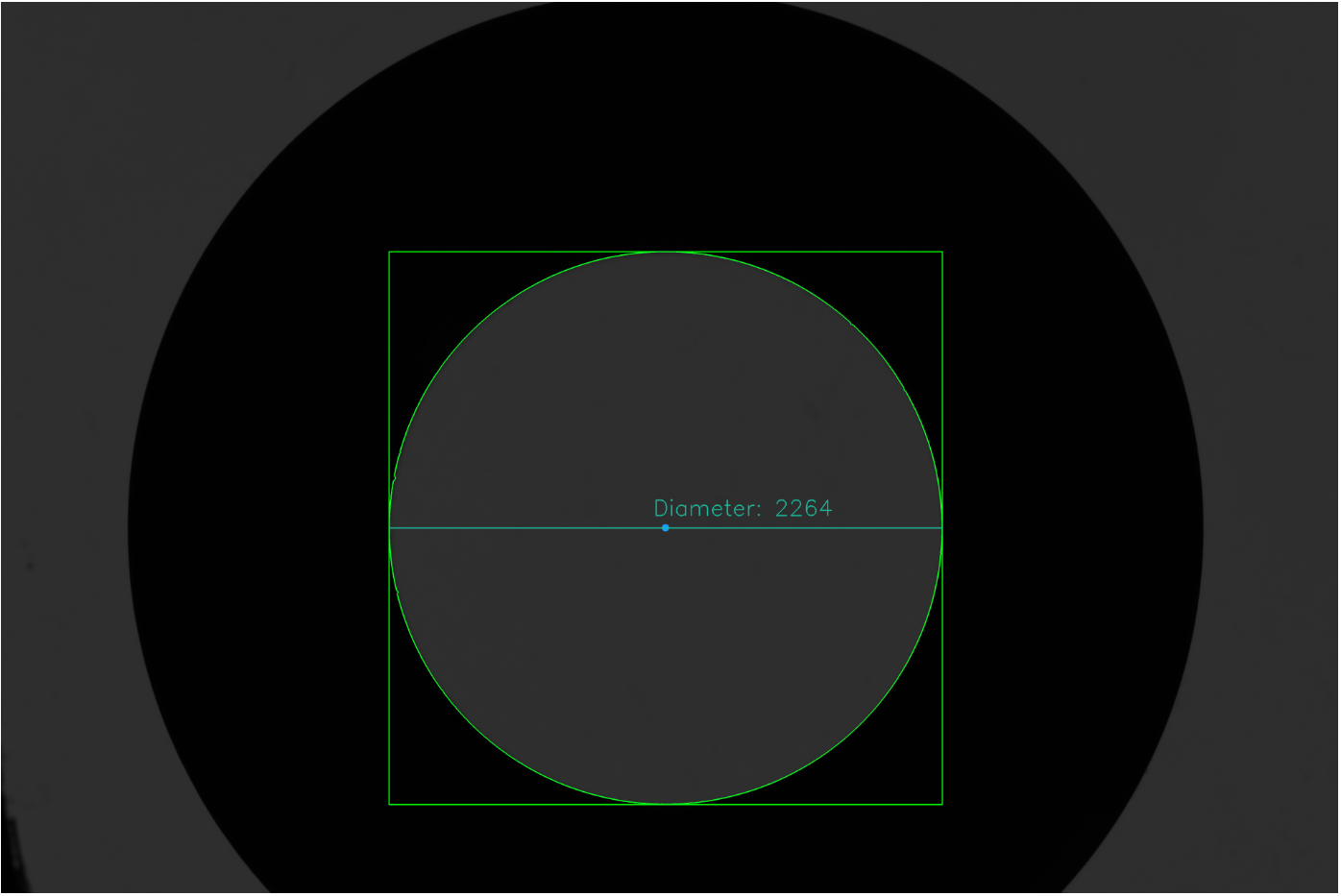
对于第二幅图像,亮度很低,给出了比需要更多的噪声图像。我需要将行bin = dip.Label(bin)修改为:
bin = dip.Label(bin, 2, 500) # Imposing minimum object size rather than filtering也许更容易做一些噪音过滤而不是。产出如下:
  |       Size |                                            Radius |
- | ---------- | ------------------------------------------------- |
  |            |        Max |       Mean |        Min |     StdDev |
  |      (µm²) |       (µm) |       (µm) |       (µm) |       (µm) |
- | ---------- | ---------- | ---------- | ---------- | ---------- |
1 |  4.023e+06 |      1133. |      1132. |      1125. |     0.4989 |

method 1: [2263.24621554]
method 2: [2263.22724164]
method 3: [2262.90068056]
方法3的快速解释
该方法用卢卡斯·范弗利特(Delft University of Technology,1993年)的PhD论文,第六章语言描述。
你可以这样想:穿过洞的光量与洞的面积成正比(实际上,它是由‘面积’x‘光强’给出的。)通过把所有通过洞的光线加起来,我们就知道了洞的面积。代码将对象的所有像素强度和对象外部的一些像素相加(我在那里使用了10个像素,距离的多少取决于模糊程度)。
erfclip函数被称为“软剪辑”函数,它保证了洞内的强度是一致的1,洞外的强度是一致的0,并且只在它留下中间灰度值的边缘附近。在这种特殊情况下,这个软剪辑避免了成像系统中的偏移和光强度估计差的一些问题。在其他情况下,这是更重要的,避免问题的不均匀颜色的物体被测量。它还减少了噪声的影响。
Stack Overflow用户
发布于 2019-07-31 21:05:10
您可以对图像进行阈值化,并使用findContours查找洞的轮廓,然后用minEnclosingCircle将圆圈与它们相匹配。通过与等高线面积的比较,可以对贴合的圆圈进行健康检查。
import cv2 as cv
import math
import numpy as np
from matplotlib import pyplot as pl

gray = cv.imread('geriausias.bmp', cv.IMREAD_GRAYSCALE)
_,mask = cv.threshold(gray, 127, 255, cv.THRESH_BINARY)
contours,_ = cv.findContours(mask, cv.RETR_LIST, cv.CHAIN_APPROX_NONE)
contours = [contour for contour in contours if len(contour) > 15]
circles = [cv.minEnclosingCircle(contour) for contour in contours]
areas = [cv.contourArea(contour) for contour in contours]
radiuses = [math.sqrt(area / math.pi) for area in areas]

# Render contours blue and circles green.
canvas = cv.cvtColor(mask, cv.COLOR_GRAY2BGR)
cv.drawContours(canvas, contours, -1, (255, 0, 0), 10)
for circle, radius_from_area in zip(circles, radiuses):
    if 0.9 <= circle[1] / radius_from_area <= 1.1:  # Only allow 10% error in radius.
        p = (round(circle[0][0]), round(circle[0][1]))
        r = round(circle[1])
        cv.circle(canvas, p, r, (0, 255, 0), 10)
cv.imwrite('geriausias_circles.png', canvas)

canvas_small = cv.resize(canvas, None, None, 0.25, 0.25, cv.INTER_AREA)
cv.imwrite('geriausias_circles_small.png', canvas_small)
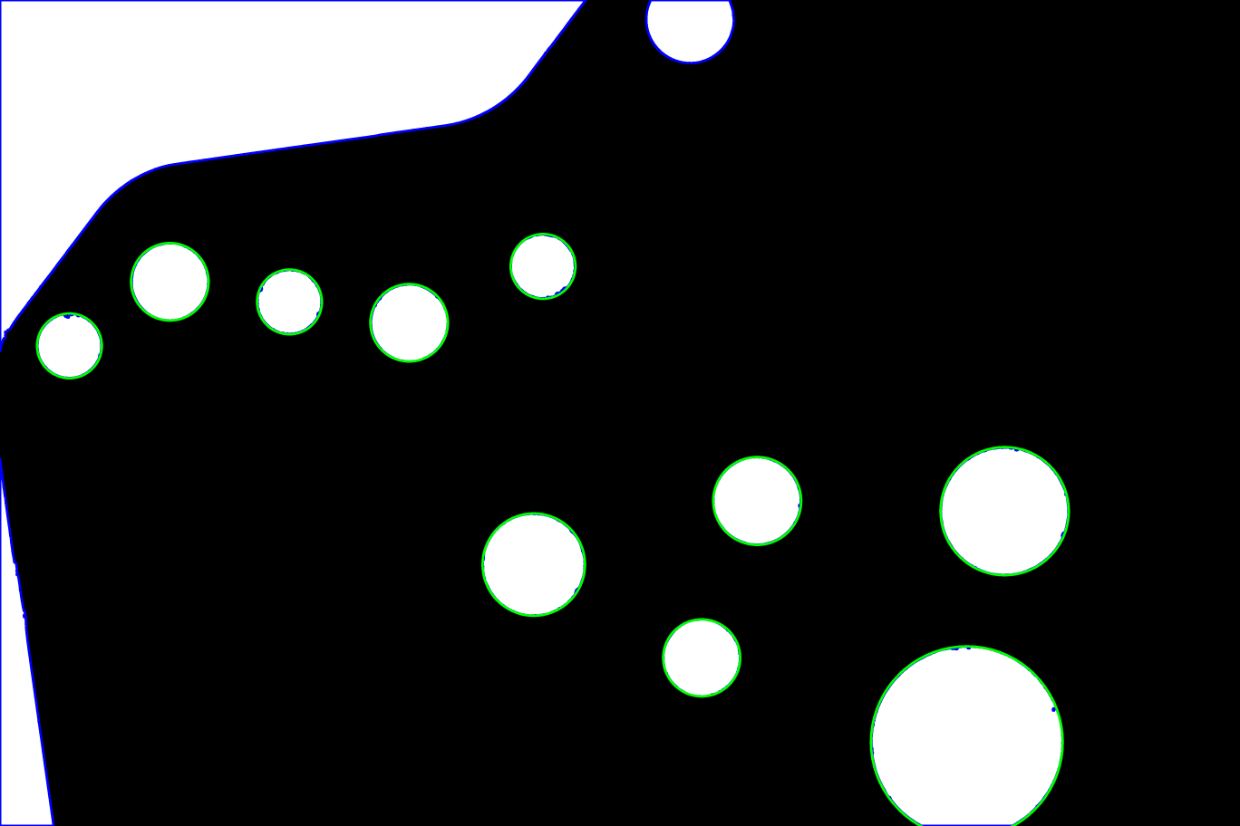
通过理智检查的圆圈在所有轮廓的顶部以绿色显示,蓝色表示。
Stack Overflow用户
发布于 2019-07-31 21:32:55
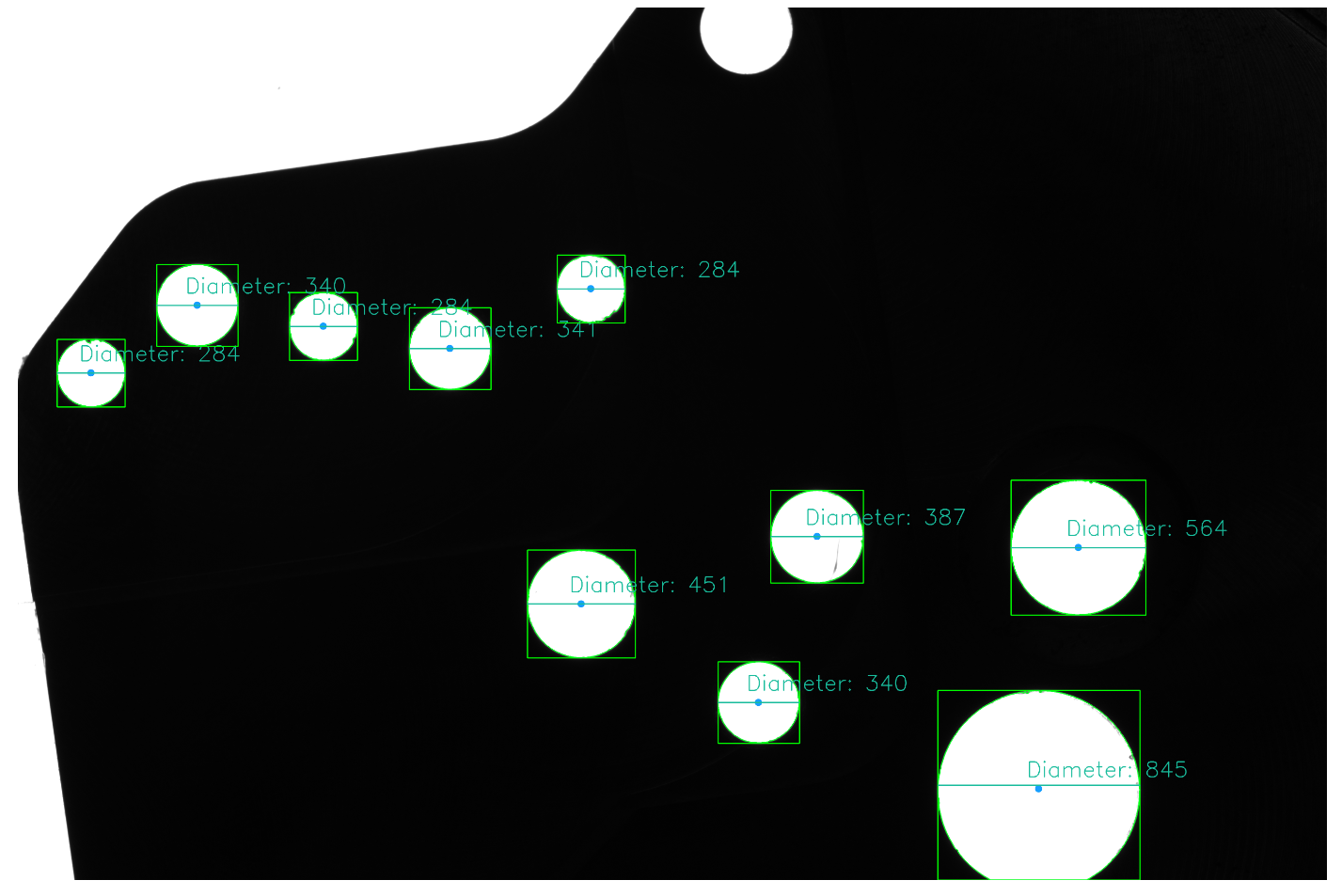
这里有个方法
- 将图像转换为灰度和高斯模糊
- 自适应阈值
- 执行形态学变换以平滑/滤波图像
- 寻找轮廓
- 求等高线周长并进行等高线逼近
- 获得边界矩形和质心来获得直径。
求出等高线后,进行等高线近似。其思想是,如果近似的轮廓有三个顶点,那么它必须是一个三角形。同样,如果它有四个,那么它必须是一个正方形或一个矩形。因此,我们可以假设,如果它有大于一定数目的顶点,那么它就是一个圆。
有几种方法可以得到直径,一种方法是找到轮廓的边界矩形并使用它的宽度。另一种方法是从质心坐标计算它。
import cv2

image = cv2.imread('1.bmp')

# Gray, blur, adaptive threshold
gray = cv2.cvtColor(image, cv2.COLOR_BGR2GRAY)
blur = cv2.GaussianBlur(gray, (3,3), 0)
thresh = cv2.threshold(blur, 0, 255, cv2.THRESH_BINARY + cv2.THRESH_OTSU)[1]

# Morphological transformations
kernel = cv2.getStructuringElement(cv2.MORPH_RECT, (5,5))
opening = cv2.morphologyEx(thresh, cv2.MORPH_OPEN, kernel)

# Find contours
cnts = cv2.findContours(opening, cv2.RETR_TREE, cv2.CHAIN_APPROX_SIMPLE)
cnts = cnts[0] if len(cnts) == 2 else cnts[1]

for c in cnts:
    # Find perimeter of contour
    perimeter = cv2.arcLength(c, True)
    # Perform contour approximation
    approx = cv2.approxPolyDP(c, 0.04 * perimeter, True)

    # We assume that if the contour has more than a certain
    # number of verticies, we can make the assumption
    # that the contour shape is a circle
    if len(approx) > 6:

        # Obtain bounding rectangle to get measurements
        x,y,w,h = cv2.boundingRect(c)

        # Find measurements
        diameter = w
        radius = w/2

        # Find centroid
        M = cv2.moments(c)
        cX = int(M["m10"] / M["m00"])
        cY = int(M["m01"] / M["m00"])

        # Draw the contour and center of the shape on the image
        cv2.rectangle(image,(x,y),(x+w,y+h),(0,255,0),4)
        cv2.drawContours(image,[c], 0, (36,255,12), 4)
        cv2.circle(image, (cX, cY), 15, (320, 159, 22), -1)

        # Draw line and diameter information
        cv2.line(image, (x, y + int(h/2)), (x + w, y + int(h/2)), (156, 188, 24), 3)
        cv2.putText(image, "Diameter: {}".format(diameter), (cX - 50, cY - 50), cv2.FONT_HERSHEY_SIMPLEX, 3, (156, 188, 24), 3)

cv2.imwrite('image.png', image)
cv2.imwrite('thresh.png', thresh)
cv2.imwrite('opening.png', opening)https://stackoverflow.com/questions/57297612
复制相似问题
腾讯云开发者
