查看网络拓扑
云防火墙提供了一个可视化视图,帮助您快速梳理 VPC 间资产的访问关系。
说明:
自定义路由方案下暂无网络拓扑图
1. 登录 云防火墙控制台,在左侧导航栏中,选择防火墙开关 > VPC 间开关。
2. 在VPC 间开关页面,单击网络拓扑,查看接入的 VPC 网络实例详情。
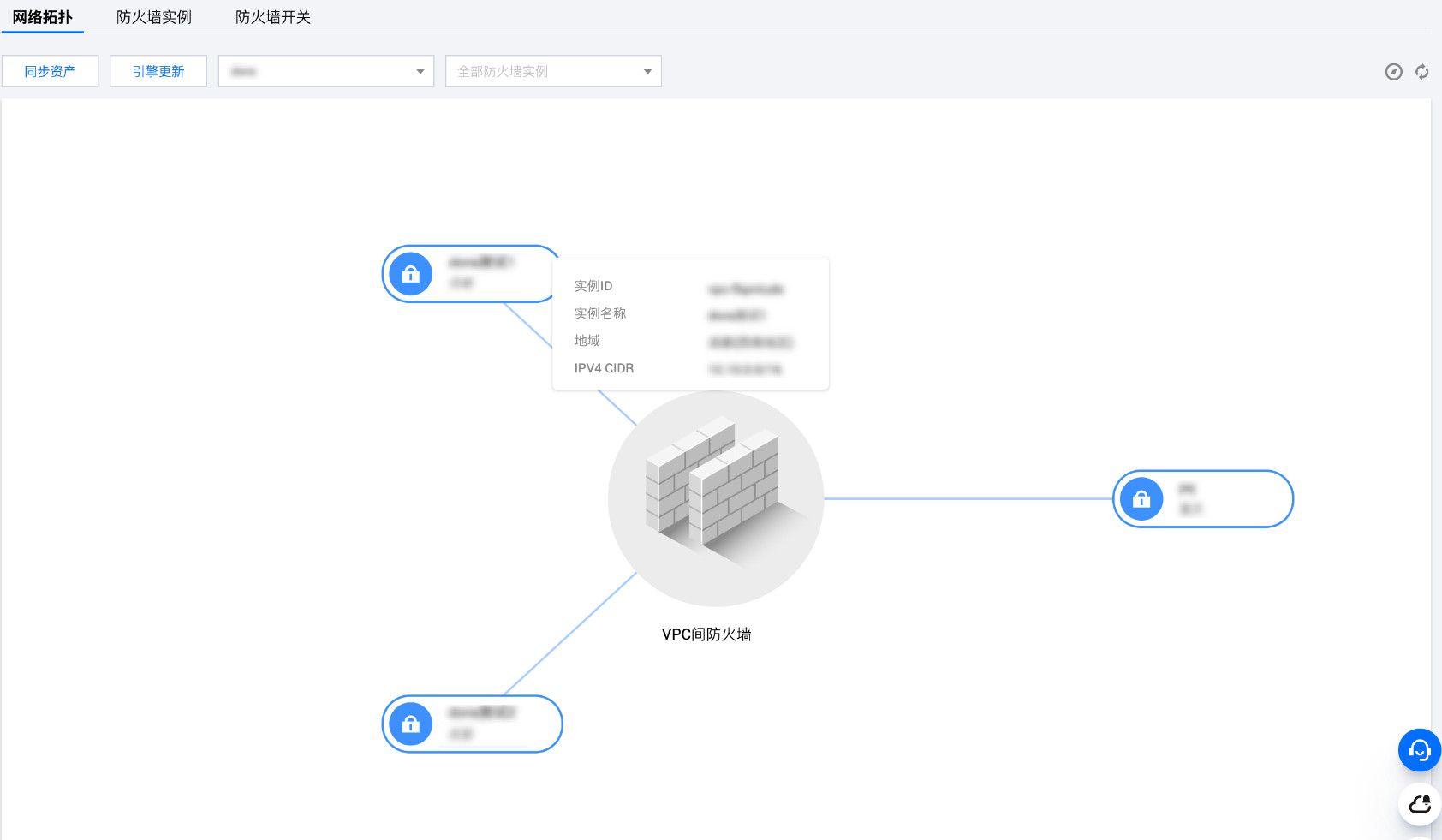
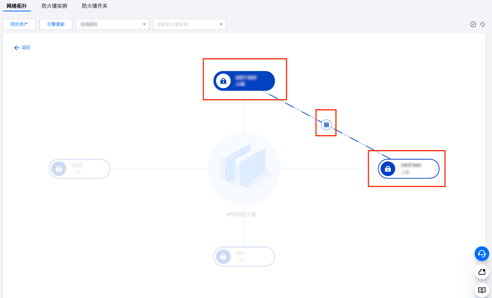
3. 在网络拓扑页面,鼠标悬停在某个 VPC 实例,可以查看该实例的详细信息。
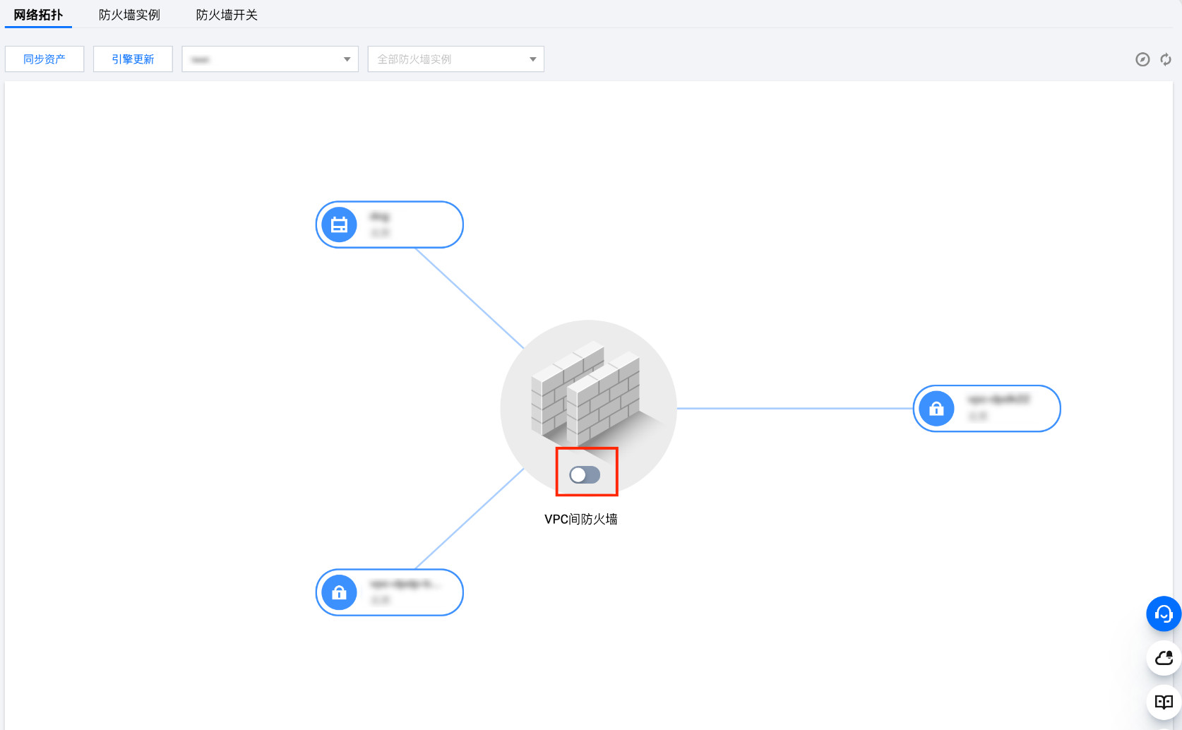
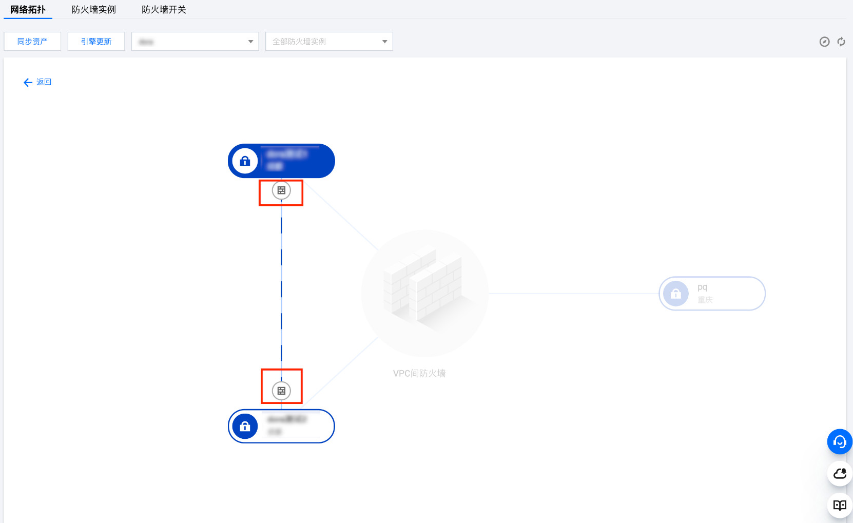
4. 单击某个实例,可查看与其他 VPC 实例的连接情况,以及防火墙开关开启情况。防火墙开关标识如果深蓝色则代表开关开启,如果是灰色则代表开关关闭。
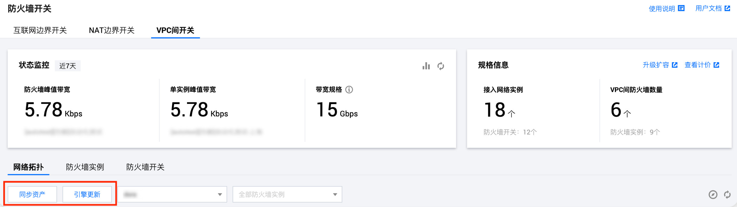
5. 在网络拓扑页面,单击同步资产,可以及时同步资产信息;将鼠标悬停引擎更新处可以查看版本信息。
6. 在网络拓扑页面,单击右上角的

使用 VPC 视图梳理 VPC 间的访问关系
云防火墙提供了一个可视化视图,帮助您快速梳理 VPC 之间的访问关系。在 VPC 可视化视图中,每个节点是一个 VPC 实例,VPC 间防火墙是一个中心化的设备,每个开关控制了不同的路由。已开启开关的 VPC 间流量将会被牵引至防火墙进行过滤与防护。
1. 登录 云防火墙控制台,在左侧导航栏中,选择防火墙开关 > VPC 间开关。
2. 在VPC 间开关页面,单击网络拓扑,查看接入的 VPC 网络实例详情。
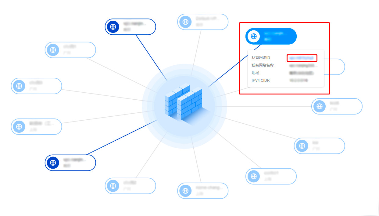
3. 将鼠标在某个 VPC 节点上悬停,可查看 VPC 的简要信息,同时与之互联的所有 VPC 也会亮起。单击私有网络 ID 的蓝色字体,可进入 VPC 详情页查看该 VPC 的详细信息。
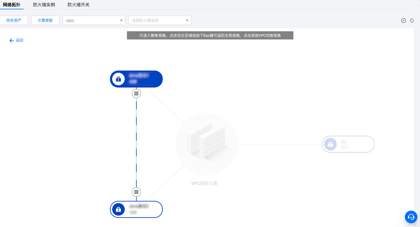
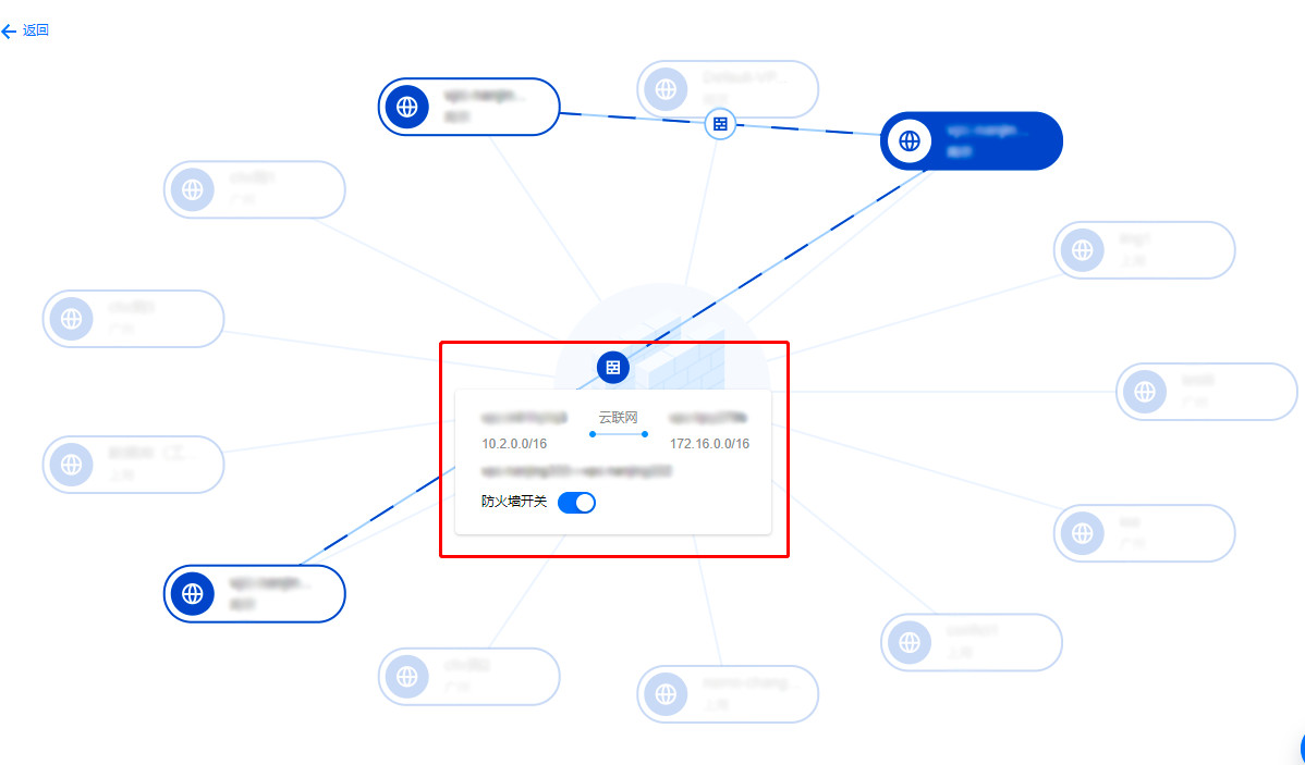
4. 可以单击某个 VPC 节点,页面进入聚焦视图,显示以聚焦 VPC 为中心的拓扑结构。
5. 彼此互通的 VPC 间通过连线相连接,连线中可以查看或操作防火墙开关,也可以通过单击防火墙的
注意
单点互通模式下每对可互相访问的 VPC 在图上仅会展示1个开关。
多点互通模式下每个 VPC 会展示1个开关。
全互通模式 VPC 间防火墙仅会有1个开关。
单点互通模式
多点互通模式
全互通模式